
British 2059
LETTERS PATENT to Bethel Burton, of the City of Brooklyn, in the State of New York, America, at present residiug with Messieurs Alexander Beil and Son, No. 8, Finch Lane, London, E.C., for the Invention of “ Improvements in Breech-loading and Revolving Fire-arms and Cannon, and Metallic Cartridges.”
Sealed the 8th November 1864, and dated the 19th August 1864.
COMPLETE SPECIFICATION filed by the said Bethel Burton at the Office of the Commissioners of Patents, with his Petition and Declaration, on the 19th August 1864, pursuant to the 9th Section of the Patent Law Amendment Act, 1852.
TO ALL TO WHOM THESE PRESENTS SHALL COME, I, Bethel Burton, uf the City of Brooklyn, in the State of New York, America, at present residing with Messieurs Alexander Bell and Son, No, 8, Finch Lane, London, E.C., send greeting.
WHEREAS I am in possession of an Invention for “ Improvements in Breech-loading and Revolving Fire-arms and Cannon, and Metallic Cartridges,” and Lave petitioned Her Majesty to grant unto me, my executors, administrators, and assigns, Her Royal Letters Patent for the same, and have made solemn Declaration that I am the true and first Inventor thereof.
NOW KNOW YE, that I, the said Bethel Burton, do hereby declare that the following Complete Specification under ray hand and seal fully describes and ascertains the nature of the said Invention, and in what manner the same is to be performed, in and by the following statement:—
My Invention has for its object improvements in breech-loading and revolving fire-arms, and also in cannon and metallic cartridges.
Firstly, my Invention has for its object improvements in breech-loading fire-arms,
Fig, 1, Sheet 1 (in the accompanying two Sheets of Drawings), is a sectional view of my improved breech-loader, and Fig. 2 is a plan of the same; Figs. 8, 4, 5, 6, 7, 8, exhibit the various parts of the breech.
This Invention is an improvement upon my former Patent (No. 1535 of the year 1859). In Fig. 1, I is the stock; K, K, K, the barrel chambered to receive the sliding breech pin 7, 7, and the sectional screw plug m, w, which is also chambered ; h is the end of the breech pin, which enters the chamber in the sectional screw plug w, w», and is fastened to it by means of a bayonet joint, as shown separately in Figs. 5, 6, and 7. In Figs. 6 and 7, d is the recess in the sectional screw plug m, m9 and n is a pin which slides into the said recess d, and thereby they are secured together; C is the bolt, as shown separately at Fig. 8; D, D, is a thimble enclosing the spiral spring 0; P is a spring attached to the under side of the chamber of the barrel, having at its end two fingers Q and R, R running up through a hole in the chamber of the barrel and working in an J -shaped slot in the sectional screw plug m, m, and when the sectional screw plug is drawn back to allow of a cartridge being inserted iuto the barrel, the spring p serves to force the finger R up in front of the thimble D, and retains it in place until released by the pressure of the trigger B upon the finger Q; this finger R working in a slot serves to guide the sectional screw in and out of place; Q, is a finger passing under the nose of the trigger B, which latter being depressed by pulling the trigger draws down the figer R, which thereby liberates the thimble D in consequence of the force of the spiral spring 0 causing the thimble to strike the bolt C, which ignites the fulminate in the cartridge by the blow; the fulminate being struck in two places by the projection S, S, on the bolt C, the ignition of the fulminate is rendered certain. The thimble D, D, which encloses the spiral spring 0, extend as far back as the finger R, thus preventing the said finger R from running up into the coils of the spiral spring 0 when in motion. F is a spring let in flush with the surface of the sliding breech pin l; this spring F is secured by a screw U, the point of which passing into a slot on the bolt C prevents the said bolt from turning when removing the nut V to clean the bolt C. When manipulating the breech without a cartridge in the barrel (he nut V prevents the bolt C from striking the barrel so as to damage it by the projections S, S. The object of the spring F is to withdraw the cartridge case from the barrel for the purpose of loading or unloading the arm, which is done by means of a hook or catch on its end, as shown separately in Fig. 4. t, t, is the sectional screw, which is fully described in my former Patent, (No. 1535, 1859,) before referred to.
The spring safety lock (Figs. 9 and 10) is attached to the side of the chamber of the barrel, the purpose of which is to prevent the premature dis* charge of the arm, and also to prevent the sectional screw plug from turning and coming back. This spring lock is fastened at one end to the chamber by a screw, and at its other end is a pin passing through the s;iid chamber. In the sectional screw plug there is a hole so placet! that when the pin on the said spring lock enters the hole the trigger is prevented from drawing down the finger R of the springy. On referring to the Drawing, Fig. 1, it will be seen that a hole is provided in the chamber of the barrel, and a slot is made in the sectional screw plug. It will now be observed that in consequence of the relative positions of the centre upon which the trigger moves and the top of the trigger, the moment the trigger is drawn back the top of the trigger necessarily describes a part of a circle, the consequence being that unless the slot in the sectional screw plug has been brought immediately over the top of the trigger it is impossible for the trigger to move in the smallest; degree, and consequently the arm cannot be discharged.
In the spring lock, Figs. 9 and 10, is formed a slot, and a pin passes up through this slot from a wedge, which wedge being pushed forward serves to force back the spring, and thereby withdraws the pin at the end of said spring lock ; then a partial revolutipn of the sectional screw plug brings the slot immediately over the top of the trigger, so that the trigger can now move and press upon the finger Q for the purpose of discharging the arm, as hereinbefore described.
My Invention next relates to further improvements in fire-arms, whereby the arm is capable of being used either as a breach or muzzle loader, in which also either paper or metallic cartridges may be used. This part of my Invention is also an improvement upon my breach-loading arm described in my former Patent, herein-before referred to.
Fig. 11 represents the arm I am now about to describe. The same letters of reference in Fig. No. 11 denote similar parts to those in Fig. No. 1, I being the stock ; K, the barrel; J, the lock; W, the hammr r ; and X, the nipple piece. Figs. 12, 13, 14, 15, and 16 represent separate parts of the improved arm. Fig. 16 is a top view and Fig. 14 is a side view of the hiding breach pin lt 7, which is provided with a spring F, similar to the spring F in Fig. 1, before described, and for the same purpose, and shewn again separately in Fig 15. This sliding breach pin is also provided with a nipple lump X, which may be inserted the ordinary screw nipple, Fig. 12, or the loose nipple, Fig 13. This sliding breach pin is connected at h with the sectional screw plug m, m, by a bayonet joint, as before described in Fig. 1. When, for economy sake, I desire to use again the metallic cartridge case recharged, I employ this nipple, Fig. 12, with a percussion cap. In this case a hole is made in the centre of the base of the cartridge, through which the fire from the percussion cap is communicated to the powder in the cartridge by means of a channel in the breach pin, shown by the dotted lines at zf Fig. 16. This is a continuation of the channel in the nipple, Fig. 12, and which said channel through the breach pin conducts the fire to the centre of the breach pin, and consequently to the hole before mentioned in the centre of the cartridge.
When I desire to use my gun as a muzzle-loader with loose powder, I leave a metallic cartridge case in the chamber of the barrel, which metallic cartridge case serves effectually to prevent all escape of gas through the breach. Fig. 13, before referred to, is a solid nipple pin, which I employ when metallic cartridge charged with fulminate in the rim are used. This nipple pin is formed with a head to prevent its passing too far down the nipple hole when there is not a cartridge in the gun, and thereby prevents its striking the barrel. With this nipple pin, as adapted to my gun, no spring is required, for as soon as the breach pin is shoved up in place the cartridge presses back the nipple pin, Fig. 13, to allow of its delivering the blow from the hammer to ignite the fulminate in the flange of the cartridge against a shoulder on the barrel, and is prevented coming out of the nipple hole by a small pin inserted in the side of the lump of the breach pin, which passes into the nipple hole and enters on a flat or slot on the side of the nipple pin, Fig. 13, which flat or slot allows of sufficient play to the said nipple pin in order to deliver the blow. This nipple pin, Fig. 13, when inserted into the breach pin, Figs. 14 and 16, works loose on the points of the screw threads in the hole in said breach pin.
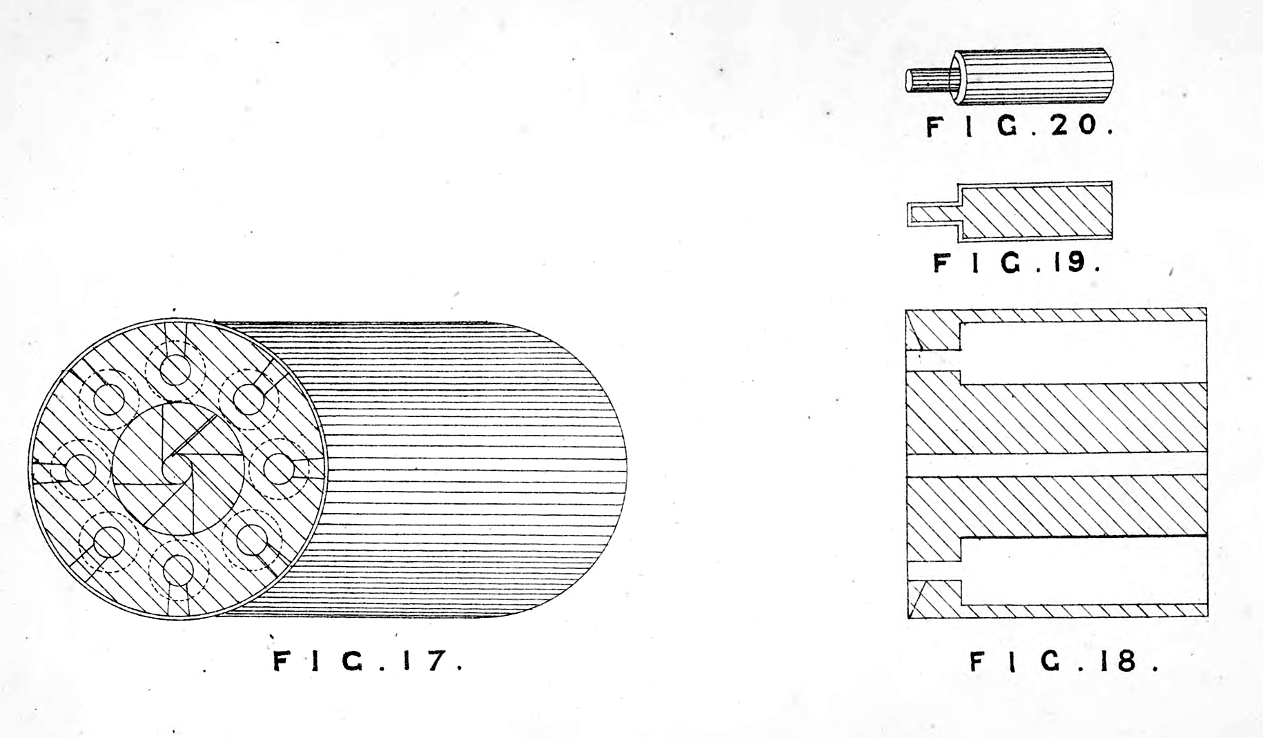
My Invention next relates to improvements in the cylinder of revolving firearms. Figs. 17 and 18, Sheet No. 2, represent my improved cylinder for a revolver. It will be seen by the section, Fig. 18, that the bore in the cylinder does not run through, but a small hole is made through the base of the cylinder which leaves a shoulder, and down into this hole qnd in the base of the cylinder a slot or grove is formed ; the purpose of this slot or grove is to allow the hammer or cock to strike the upper side of the cartridge, and the purpose of ike small bole is to leave a shoulder to prevent the metallic cartridge from being forced back against the frame of the arm or pistol, and so preventing its revolving. Figs. 19 and 20 represent the cartridge I adopt for this cylinder. The case is of copper or other soft metallic substance. This form of cartridge admits of priming with much greater ease than the cartridges now in use, which have the priming in the rim, and which require the greatest care to insure their being primed all around the rim. My cartridge is primed in the usual manner of priming percussion caps, and can be done with a certainty, and by its fitting the cylinder is prevented from swelling between the cylinder and the frame of the arm which occurs in the arms, and has a tendency to prevent the freedom of revolving. This cartridge may also be ignited by means of a percussion cap upon its neck, with a hole in the base of the neck of the cartridge to admit the fire from the cap to the powder, the percussion cap being struck in the usual way.
My Invention relates, lastly, to certain improvements in cannon of cast metal. Fig. 21, Sheet 2, is a longitudinal section of my improved cannon, in which A, A, is the cast metal; B, B, the jacket of wrought iron or cast steel, on which are placed the trunnions F, F ; C, C, is a nut of wrought metal or tteel screwed around the cast metal forming a shoulder. This nut forming a shoulder prevents the recoil of the gun from forcing the cast metal through the jacket B, B. This jacket B, B, beiijg largely tapering (as is also the cast metal) serves to assist the cast metal in resisting the lateral as well as the backward strain produced by the explosion of the charge. The nut or shoulder C, C, being screwed on to the cast metal is capable of being so adjusted from time to time as to leave just sufficient spacQ between it and the jacket to check the effect of the possibly too great elasticity of the jacket B, B, in aiding the cast metal A, A, to assist the explosive force of the charge. The effect of the explosion being to force back the cast metal like a wedge into the jacket, by this means I transfer the strain to the jacket, and thus I prevent the fracture of the cast metal which results in ordinary cast guns from the repeated discharges. D, D, is a lining of steel or wrought iron throughout the bore of the gun. This lining fits the bore of the gun, which bore in the cast metal I make of such a form (as, for example, of an oval or octagonal section) to prevent the lining D, D, from revolving by the action of the projectile upon the rifling of the said lining in passing out of the gun. For the purpose of removing and replacing the lining D, D, when its rifling is worn out, I introduce at the breach a screw E, which screw being taken out gives access to the breach of the lining, to which I apply hydraulic pressure or other suitable means to remove the said lining. The lining is made stronger at the base than elsewhere to enable it to endure the force thus applied to remove it. In casting the gun the whole into which the screw E is inserted serves as a passage for a stream of water for the purpose of securing an equal contraction of the metal in cooling.
It is to be understood that I do not confine myself to the exact dimensions, proportions, or configurations given in the accompanying Drawings.
I claim as my Invention the combination of parts shewn in the accompanying Drawings, and herein particularly described and set forth.
With respect to my breach-loading fire-arms, as above described, I claim as my Invention the spiral spring 0, 0, Fig. 1, working in the chamber of the sectional screw plug m, m9 in combination with the thimble D, D, as described.
I claim also the bolt C, with the two projections or points S, S, on its head, for the purpose of striking the fulminate, as described.
I claim also the spring catch F and the screw U, as described.
I claim also the method of fastening the end cf the sliding breach pin h to the sectional screw plug w, wt, by the bayonet joint, as described.
I claim also the fingers Q, and R upon the springy), as described.
I claim also the trigger B, as described.
I claim also the spring lock, Figs. 9 and 10, as described.
I claim also the nipples, Figs. 12 and 13, and their employment in the some nipple hole, Figs. 14 and 16, as described.
With respect to my improvements in revolving firearms, as above described, I claim the cylinder for revolving fire-arms, Figs. 17 and 18, and the cartridge for the same, Figs. 19 and 20, as described.
With respect to my improvements in cannon, as above described, I claim the nut C, C, the jacket B, B, and the screw E, as described.
I claim also the form of the bore of the cast metal A, A, and the manner of lining the same.
In witness whereof, I, the said Bethel Burton, have hereunto set my hand and seal, this Nineteenth day of August, in the jear of our Lord One thousand eight hundred and sixty-four.
Witness to the signature of Bethel Burton,
Frederick Trotman.
BETHEL BURTON