
Britain 5504
A.D. 1881, 16h December. № 5504.
Locks of Fire-arms.
LETTERS PATENT to Edouard Bled and Edmond Richoux, both of Paris, in the Republic of France, Gentlemen, and Jean Warnant, of Liege, in the Kingdom of Belgium, Fire-arm Manufacturer, for an Invention of “Improvements in the Locks of Fire-Arms.”
PROVISIONAL SPECIFICATION left by the said Edouard Bled, Edmond Richoux, and Jean Warnant at the Office of the Commissioners of Patents on the 16th December 1881.
Edouard Bled and Edmond Richoux both of Paris in the Republic of France, Gentlemen and Jean Warnant, of Liege in the Kingdom of Belgium, Fire-arm Manufacturer,”Improvements in the Locks of Fire-Arms.”
Our Invention relates to improvements in the locks of fire arms and are more particularly adapted for revolving fire arms.
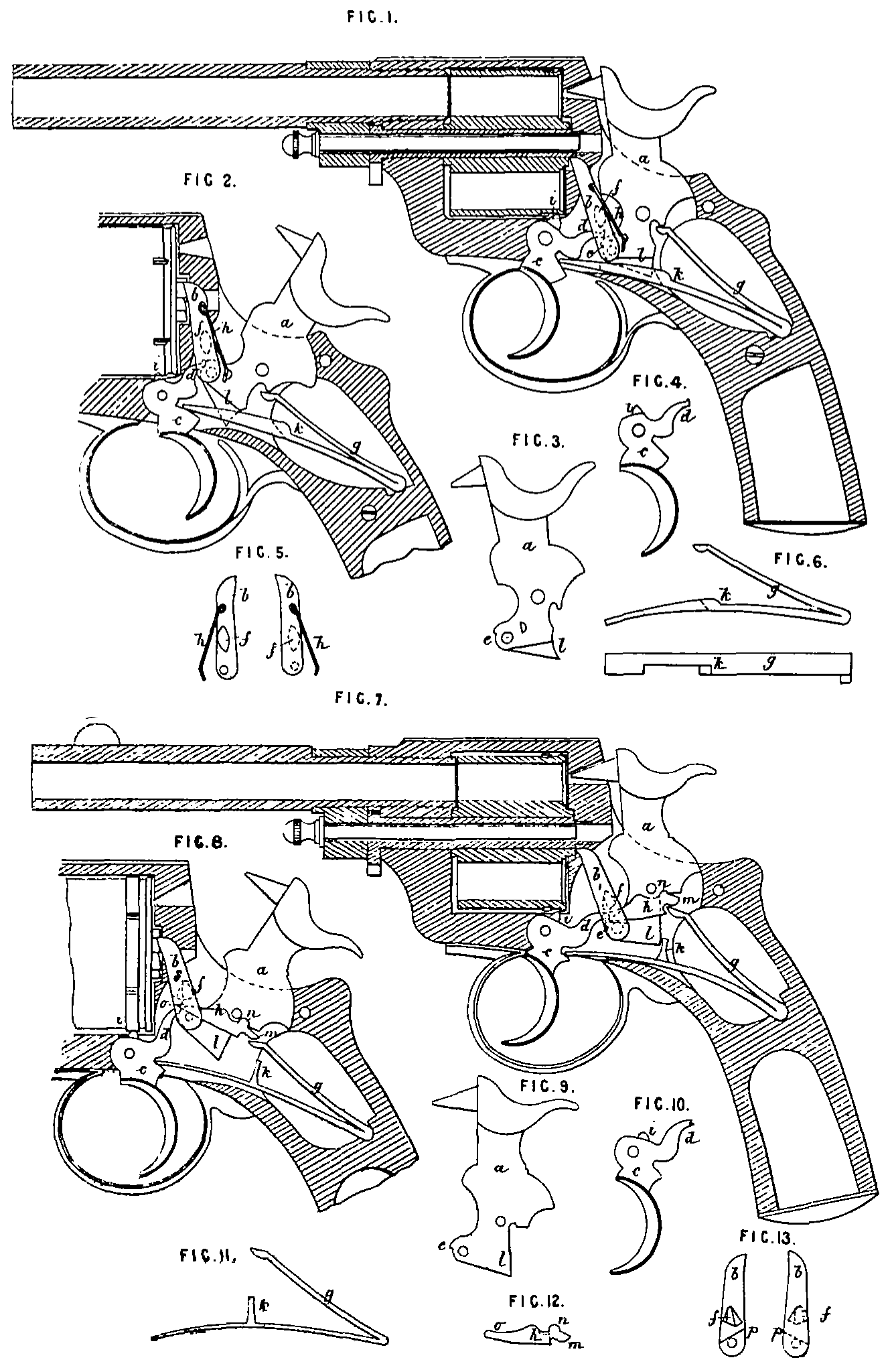
The accompanying Drawings show two specimens of revolvers made according to our Invention, Figure Lisa longitudinal central section of a revolving pistol, the hammer being at half cock. Figure 2 shows a similar section, the hammer being raised to full cock by the thumb, Figures 3, 4, 5, and 6 show the different parts of the lock separately. Figures 7 and 8 are longitudinal central sections of another revolver slightly different from the first, the hammer being at half cock and full cock respectively, Figures 9,10, 11, 12,13 show the parts of the lock separately. In all Figures the same letters of reference indicate similar parts.
a is the tumbler and hammer in one carried on a pivot made in one piece with the frame of the revolver. The tumbler has a pawl b pivoted to it to engage with ratchet teeth on the cylinder and cause it to revolve. c is the trigger, the point of which is made in one piece with the frame of the revolver. The trigger c has a nose or projection d which passes between the lower part e of the tumbler and a lug f on the side of a pawl b, g is a double branched main spring of which the lower branch acts directly upon the trigger, and the upper branch acts upon the tumbler and hammer either directly as in Figure 1, or it may be made (as in Figure 7) to press against a small lever h whose front end at the same time presses upon the inclined shoulder p of the pawl bin order to keep it up to the cylinder, thereby dispensing with the small spring h used for this purpose in Figure 1.
The operation of the lock is as follows:— When the trigger c is pressed back, its nose d takes under the lug f of pawl b and thereby raises the hammer to full cock at same time causing the cylinder to revolve. When the trigger is pulled quite back, the nose d escapes from the lug f thereby freeing the pawl b and hammer a and allowing them to be brought down by the spring (g, thus firing the cartridge. The cylinder is held in its position as usual by the projection i on the trigger at the time of firing.
The trigger when released from the pressure of the finger is returned to its first position by the pressure of the lower part of spring g, and during that movement its nose d comes in contact with the top of lug f and pushes back the pawl b so as to allow nose d to pass and again take under lug f.
The lower branch of spring g is made with a catch k so that during its down-ward motion it presses upon a downward projection l of the tumbler a and raises the hammer to half cock automatically.
The lever k shown in Figures 7 and 8 is pressed upwards at m by the upper branch of spring g and is thus kept in contact with the tumbler at. The parts in contact are so shaped as to allow a slight oscillation of the lever k upon the projection n as a fulcrum, the long arm o of the lever pressing upon a shoulder p on the side of the pawl d which is thus kept constantly up to the cylinder.
When the hammer is cocked directly by the thumb, the operation of the lock is slightly different. In this case part e of the tumbler lifts up the nose d of the trigger until it engages in the notch at e as in Figures 2 and 8, and holds the hammer at full cock. When the trigger is pulled the hammer is released and brought down by the spring g.
SPECIFICATION in pursuance of the conditions of the Letters Patent filed by the said Edouard Bled, Edmond Richoux, and Jean Warnant in the Great Seal Patent Office on the 16th June 1882.
Edouard Bled and Edmond Richoux both of Paris in the Republic of Franco Gentlemen and Jean Warnant of Liege in the Kingdom of Belgium, Fire-arm Manufacturer. “Improvements in the Locks of Fire-Arms.”
Our Invention relates to improvements in the locks of fire arms particularly revolving fire arms.
The accompanying Drawings show two specimens of revolvers made according to our Invention. Figure 1 is a longitudinal central section of a revolving pistol, the hammer being at half cock. Figure 2, shows a similar section, the hammer. being raised to full cock by hand. Figures 3, 4, 5 and 6 show the different parts of the lock separately. Figures 7 and 8 are longitudinal central sections of another revolver slightly different from the first, the hammer being at half cock and full cock respectively. Figures 9, 10, 11, 12, 13 show the parts of the lock separately, Tn all Figures the same letters of reference indicate similar parts.
a is the tumbler and hammer in one, carried on a pivot made in.one piece with the lock frame. The tumbler has a pawl l pivoted to it, which is pressed by a spring h into engagement with ratchet teeth on the end of the cylinder and causes it to revolve. cis the trigger, working on a pivot made in one piece with the frame of the revolver. The trigger c has a nose or projection d which passes between the lower part e of the tumbler and a peculiarly shaped lug f on the side of the pawl 6. gi s a double branched main spring of which the lower branch acts directly upon the trigger, and the upper branch acts upon the tumbler and hammer either directly as in Figure 1, or as in Figure 7, through the intervention of a small lever k which answers the purpose of the spring h in Figure 1.
The operation of the lock is as follows:— When the trigger c is pressed back, its nose c takes under the lug f and raises pawl b, thereby causing the cylinder to revolve and at same time raising the hammer. When the trigger is pulled quite back, the nose d escapes from the lug f freeing the hammer and allowing it to be brought down by the spring g, thus tiring the cartridge.
The cylinder is held in its position as usual by the projecting nib i on the trigger at the moment of the discharge. The trigger when released by the finger is returned to its first position by the pressure of the lower part of spring g, and during that movement its nose d comes in contact with the top of lug f and pushes back the pawl b so as to allow the nose d to pass beneath and again take under lug f.
The lower branch of spring g is made with a should or lug k so that during its downward motion it presses upon a downward projection J of the tumbler a and raises the hammer to half cock automatically. The lever h shown in Figures 7 and 8 is pressed upwards at m by the upper branch of spring g and is thus kept in contact with the tumbler at n. The parts in contact are so shaped as to allow a slight oscillation of the lever h upon the projection m as a fulcrum, the long arm o of the lever pressing upon an inclined shoulder p (see Figure 13) at one side of the paw! 6 which is thus kept constantly up to the cylinder.
When the hammer is cocked directly by the thumb, the operation of the lock is slightly different. In this case part e of the tumbler lifts up the nose d of the trigger until it engages in the notch at e as shown in Figures 2 and 8, and holds the hammer at full cock. When the trigger is pulled the hammer is released and brought down by the spring g.
Having described the nature of our Invention of “Improvements in the Locks of Fire Arms” and the manner of performing the same we declare that what we claim as our Invention to be protected by the hereinbefore in part recited Letters Patent is
1st. In combination with the hammer, tumbler, pawl and trigger as described, the double spring g the lower branch of which acts directly upon the trigger c substantially as and for the purpose specified.
2nd. In combination with the hammer, tumbler, spring, and trigger acting as described, the pawl b pivoted on the hammer and provided with a lug f, so as to be lifted up by the projection d of the trigger which is allowed to come down again to its first position by the pawl b yielding back to let it pass, substantially as and for the purpose specified.
3rd. In combination with the hammer, tumbler, spring, pawl and trigger as described, the oscillating lever A fulcrumed against the tumbler at 7 and transmitting thereto the pressure of spring g at the same time that its arm o acts on the shoulder p of the pawl and keeps it up to the cylinder substantially as shown and described.
In witness whereof I the said Edouard Bled for myself and on behalf of the said Edmond Richoux and Jean Warnant have hereunto set my hand and seal this Twelfth day of June, A.D, 1882
EDOUARD BLED. (L.S.)