
Britain 5520
A.D. 1881, 16th December. № 5520.
Locks of Fire-arms.
LETTERS PATENT to Edouard Bled and Edmond Richoux, both of Paris, in the Republic of France, Gentleman, and Jean Warnant, of Liege, in the Kingdom of Belgium, Fire-arm Manufacturer, for an Invention of “Improvements in the Locks of Fire-arms.”
PROVISIONAL SPECIFICATION left by the said Edouard Bled, Edmond Richoux and Jenn Warnant at the Office of the Commissioners of Patents on the 16th December 1881.
Edouard Bled and Edmond Richoux both of Paris in the Republic of Franco Gentlemen and JEAN Warnant of Liege in the Kingdom of Belgium, Fire-arm Manufacturer. “Improvements in the Locks of Fire-arms.”
Our Invention relates to improvements in the locks of all kinds of fire arms, but more particularly of revolvers.
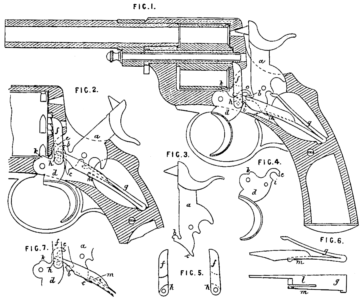
In the accompanying Drawings we have shown a revolving pistol made according to our Invention. Figure 1 is a central longitudinal section, the hammer being at half cock. Figure 2 shows part of the same section with the hammer at full cock. Figures 3. 4. 5 and 6 represent the parts of the lock separately. Figure 7 illustrates the action of the spring in raising the hammer to half cock. In all the Figures the same letters of reference indicate identical parts.
a is the tumbler and hammer in one provided with a projecting nose b and with a rear projection c to be acted on by the main spring for raising the hammer to half cock as hereafter described. dis the trigger provided with a curved nose or projection e adapted to be lifted by the nose b of the tumbler when the hammer is full cocked by the thumb. f is a pawl pivoted to the trigger and engaging with ratchet teeth on the rear of the cylinder in order to rotate it and bring its chambers successively in line with the hammer, g is a double branched main spring. The upper branch takes directly under the hammer while the lower branch is extended so as to press on an inclined shoulder k upon the pawl f whereby to keep the pawl up to the revolving cylinder and press the trigger d downwards, The lower branch of the spring g has a flat part l which is slit to form a spring portion m, as shown in Figure 6, to act on the projection c of the tumbler.
The action of the lock is as follows:— When the trigger d is pulled, its shoulder i takes under the nose b and lifts the hammer until i escapes from b whereupon the hammer falls by the action of the upper branch of the main spring g and fires the cartridge, the cylinder being meanwhile held in the proper position by a projection & on the trigger engaging in one of the notches cut around its circumference. The trigger on being released from the pressure of the finger is returned to its first position by the pre-sure of the lower branch of the main spring g upon the shoulder h. During this return movement of the trigger, the flat part l of the lower branch of spring g comes down in contact with the projection ¢ of the tumbler, but as the extremity of the small spring portion m is enlarged and rounded, whilst that of the flat part l is bevelled, the spring m touches first and is slightly bent as is shown in Figure 7. Now ag the downward motion of the lower branch of spring g is continued, the angle of the projection c with the flat part l is altered, the spring m exerts more leverage and acquires sufficient power to move the projection ca little lower and push it away from the flat part l as is seen in Figure 1, thereby raising the hammer until the shoulder i of the trigger takes under the nose 6 and the extremity of projection e comes into contact with the top of basin Figure 1. The hammer is then at half cock ready for the next movement. If instead of being raised by the trigger, the hammer were to be cocked by the thumb the nose b would lift the projection e of the trigger until the one engages in the notch of the other as shown in Figure 2.
SPECIFICATION in pursuance of the conditions of the Letters Patent filed by the said Edouard Bled, Edmond Richoux, and Jean Warnant in the Great Seal Patent Office on the 16th June 1882.
Edouard Bled and Edmond Richoux both of Paris in the Republic of France, Gentlemen, and Jean Warnant of Liege in the Kingdom of Belgium, Fire-arm Manufacturer “Improvements in the Locks of Fire-arms.”
Our Invention relates to improvements in the locks of all kinds of fire-arms, but more particularly of revolvers.
In toe accompanying Drawings we have shown a revolving pistol made according to our Invention, Figure 1 is a central longitudinal section, the hammer being at half cock. Figure 2 shows part of the same section with the hammer at full cock, Figures 3, 4. 5. and 6 represent the parts of the Jocks separately. Figure 7 illustrates the action of the spring in raising the hammer to half cock. In all the Figures the same letters of reference indicate identical parts.
a is the tumbler and hammer in one provided with a projecting nose b and with a rear projection ¢ to be acted on by the main spring for raising the hammer to half cock as hereafter described. dis the trigger provided with a curved nose or projection e adapted to be lifted by the nose b of the tumbler when the hammer is full cocked by the thumb. f is a pawl pivoted to the trigger and engaging with ratchet teeth on the rear of the cylinder in order to rotate it and bring its chambers successively in line with the hammer. g is a double branched wain spring. The upper branch takes directly under the hammer while the lower branch is extended so as to press on an inclined shoulder h upon the pawl f whereby to keep the pawl up to the revolving cylinder and press the trigger d downwards. The lower branch of the spring g has a flat part l which is slit to form a spring portion m as shown in Figure 6 to act on the projection c of the tumbler.
The action of the lock is as follows:— When the trigger d is pulled, its shoulder i takes under the nose b and lifts the hammer until i escapes from b, whereupon the hammer falls by the action of the upper branch of the main spring g and fires the cartridge, the cylinder being meanwhile held in the proper position by a projection k on the trigger engaging in one of the notches cut around its circumference. The trigger on bring released by the finger is returned to its first position by the pressure of the lower branch of the main spring g upon the shoulder h. During this return movement of the trigger the flat part ¢ of the lower branch of spring g comes down in contact with the projection c of the tumbler, but as the extremity of the small spring portion m is enlarged and rounded whilst that of the flat part l is bevelled, the spring m touches first and is slightly bent as is shown in Figure 7. Now as the downward motion of the lower branch of spring g is continued, the angle of the projection c with the flat parted is altered, the spring m exerts more leverage and acquires sufficient power to move the projection c a little lower and push it away from the flat part l as is seen in Figure 1, thereby raising the hammer until the shoulder i of the trigger takes under the nose b and the extremity of projection e comes into contact with the top of b, as in Figure 1. The hammer is then at half cock ready fur the next movement. If instead of being raised by the trigger the hammer were to be cocked by the thumb, the nose b would lift the projection e of the trigger until the one engages in the notch of the other, as shown in Figure 2.
In applying the Invention to other than revolving fire-arms, the pawl f would be dispensed with and the extension of the lower branch of spring g would be made to act directly upon the trigger d.
Having described the nature of our Invention of “Improvements in the Locks of Fire-arms” and the manner of performing the same, we declare that what we claim as our Invention to be protected by the hereinbefore in part recited Letters Patent is.
1st. In combination with the hammer a as described, the trigger d made to act directly on the said hammer and lift it up without using any intermediate piece, substantially as shown and described.
2nd. The small spring m formed with the main spring g and acting as described to allow the trigger to pass again under the hammer when the said hammer is brought to half cock.
3rd. In combination with the hammer a and trigger d as described, the double branched spring g, the lower branch of which is provided with a flat part l having a small spring m formed with it as and for the purpose specified.
In witness whereof I the said Edouard Bled for myself and on behalf of the said Edmond Richonx and Jean Warnant have hereunto set my band and seal this Twelfth day of June, A.D, 1882.
EDOUARD BLED. (L.S.)