
Britain 5569
A.D. 1881, 20th December. № 5569,
Revolving Cylinder Fire-arms.
LETTERS PATENT to William Robert Lake, of the Firm of Haseltine, Lake, & Co., Patent Agents, Southampton Buildings, London, for an Invention of “Improvements in Revolving Cylinder Fire-arms.” A communication from abroad by Joseph Hawes Wesson, of Springfield, Massachusetts, United States of America.
COMPLETE SPECIFICATION filed by the said William Robert Lake at the Office of the Commissioners of Patents on the 20th December 1881.
William Robert Lake, of the Firm of Haseltine, Lake, and Co., Patent Agents, Southampton Buildings, London. “Improvements in Revolving Cylinder Fire-arms.” A communication from abroad by Joseph Hawes Wesson, of Springfield, Massachusetts, United States of America.
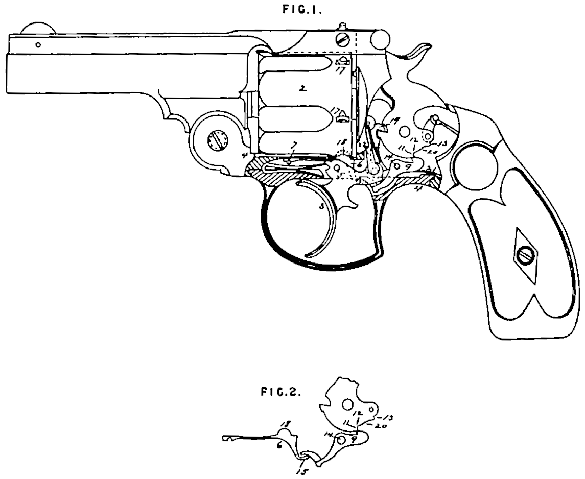
The object of this Invention is to provide a cylinder-stop for a revolver or revolving cylinder fire-arm which is cheap, durable, and effective in its construction and operation, and is controlled in its engagements with the cylinder by the hammer-tumbler through the medium of the rear sear, with which the stop that extends through or past the trigger is immediately connected; this object I accomplish by the construction hereinafter described and illustrated in the accompanying Drawing, in which
Figure I. is a side view of a revolver or revolving cylinder fire-arm with the lower portion of the frame broken away to more clearly shew the application of my Invention thereto, and
Figure II. is a side view of the cylinder-stop, the sear and the hammer-tumbler in the relative positions they occupy in-the arm, and their immediate connection with each other.
In this Drawing I have shewn my Invention as applied to a double acting revolver, in which 4 is the frame containing the revolving chambered cylinder 2, and 1 is the barrel pivotted to the front lower portion of the said frame. The trigger 3 is pivoted in the frame at 5, and is connected at its rear end with the front sear 19; the said trigger is either halved or mortised in its rear upper part in a direction lengthwise of the arm to permit the rear portion of the cylinder-stop to extend through or past that portion of the said trigger, as shewn in dotted lines in Figure 1.
The cylinder-stop 6 is made in the form of a spring, or is elastic at its forward part, and is secured at its front end firmly in the frame by a pin 7. The rear portion of the said stop is provided with an upwardly extending protuberance 18 adapted to engage with the stop-notches 17 in the rear exterior portion of the cylinder, the lower rear part 15 of the said stop extending through or past the recess made in the rear portion of the trigger.
The rear scar 9 is pivoted in the frame ‘at 14 as usual, and extends forward into such a position and sufficiently far to engage with and depress the rear portion of the cylinder-stop, as shewn in Figure IE. and in dotted lines in Figure I. The rear end of the said sear 9 is provided with the ordinary catch to engage with the hammer-tumbler, and the latter is provided with the ordinary recess 20, which in this case is provided at one end with a short straight notch 11, and inside of that with a short incline 12; at the other end of said recess is a shoulder 13 which may be more or less inclined as desired. A spring 21 may be secured in any desired manner in the frame to engage with and press the rear end of the sear 9 upward and into contact with the hammer-tumbler.
When the hammer is down, the rear end of the sear 9 bears up against the hammer-tumbler, as shewn clearly in Figure I, and the cylinder-stop is then in engagement with one of the cylinder-notches and the cylinder held stationary. If the trigger is then pressed back, the front sear 19 pivoted in the rear end of the said trigger moves the hammer backward a little in its cocking movement, and the rear end of the sear 9 is forced up into engagement with the short straight notch 11 by the action of the sear-spring 21, the hammer being then in its safety position or at half cock, and the cylinder-stop being still in engagement with the notch in the cylinder. As the trigger is pressed still farther back, the hammer is moved still farther backward in its cocking movement by the front sear 19, and the catch on the rear end of the sear 9 rides up the short incline 12, which movement causes the front end of the sear 9 to depress the cylinder-stop and disengage it from the cylinder, which is then free to be revolved by the upward movement of the hand 22, also connected with or pivoted to the trigger. As the backward cocking movement of the hammer continues when the shoulder 13 comes in contact with the rear end of the sear 9 it depresses it, raising its front end, and allowing the cylinder-stop to move up against the cylinder and enter the next notch to hold it stationary.
It will thus be seen that in all these movements the action and movement of the cylinder-stop are caused by and communicated from the hammer-tumbler through the medium of the sear 9 directly past and independent of the trigger, the latter having no connection whatever with the said cylinder-stop.
It is evident that this Invention is equally applicable to any ordinary revolving cylinder fire-arm, as well as to what is known as a double acting revolver, although, as above stated, FI have illustrated it as applied to the latter.
Having thus fully described the said Invention as communicated to me by my foreign correspondent, and the manner of performing the same, I wish it understood that I claim,—
In a revolving cylinder fire-arm.
First. The combination of the hammer, the cylinder-stop, and the sear, substantially as above described.
Second. A cylinder-stop secured in the frame and arranged to engage with the cylinder, and extending rearward past the trigger, and adapted to be operated independently thereof, substantially as above described.
In witness whereof, I, the said William Robert Lake, have hereunto set my hand and seal, this Twentieth day of December, in the year of our Lord One thousand eight hundred and eighty one.
Wᴹ. ROBᵀ. LAKE (L.S.)