
Britain 5564
A.D. 1881, 20th December. № 5564.
Revolving Fire-arms.
LETTERS PATENT to William Stringfellow, of Mistley, in the County of Essex, for an Invention of “Improvements in Revolving Fire-arms.”
PROVISIONAL SPECIFICATION left by the said William Stringfellow at the Office of the Commissioners of Patents on the 20th December 1881.
William Stringfellow of Mistley in the County of Essex. “Improvements in Revolving Fire Arms.”
The object of my Invention is to produce a revolving fire arm that can discharge shot, smooth or rifled balls, shell or other projectiles from the same set of revolving chambers, and with great rapidity. With this object I make a disc of metal containing ten or more or less chambers in the periphery thereof; which chambers are shaped to receive the cartridges required. The mouths of these chambers also project a little way beyond the periphery of the disc. This disc is mounted horizontally on the fire arm in such a manner that it can revolve with its periphery near the end of the barrel of the fire arm, and also that it is capable of a forward motion when required to allow the projecting mouths of the chambers in turn to enter the barrel. The disc is enclosed in a suitable casing made of whatever material I prefer, and in the rear of the casing 1 may make an aperture, capable of being closed, through which I can load the different chambers; or the loading thereof may be performed in any other convenient way. The firearm is discharged by an action that first forces the mouth of one of the chambers into the barrel, then gives the percussion or other force that discharges the cartridge in the said chamber, and then allows the disc to fall back, freeing the mouth of the chamber from the barrel and allowing the disc to revolve and present another chamber to the barrel ready for firing. Any suitable catches may be employed to lock either the action or the disc or both if required.
SPECIFICATION in pursuance of the conditions of the Letters Patent filed by the said William Stringfellow in the Great Seal Patent Office on the 19th June 1882.
William Stringfellow of Mistley in the County of Essex. “Improvements in Revolving Fire Arms.”
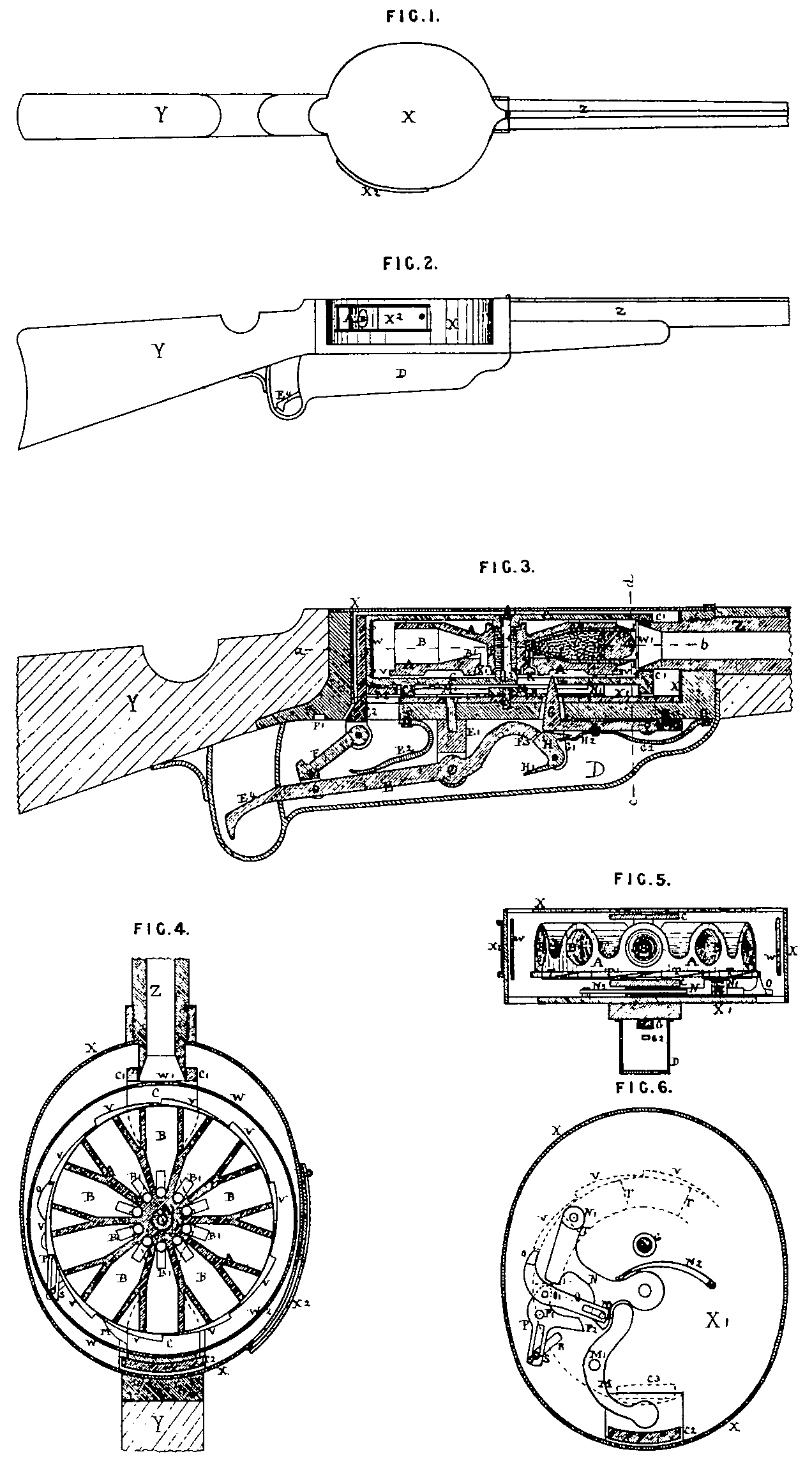
My Invention provides for the rapid discharge of the successive charges and reduces the weight of the fire arm having regard to the number of charges that can be contained therein at one and the same time, while simplifying the various actions. In order that my Invention may be clearly explained and understood I refer to the accompanying Drawing which shews the application of my Invention refer to the accompanying Drawing which shews the application of my Invention to a rifle or shot gun, Figure 1 is a plan of the upper surface of a rifle or shot gun. Figure 2 is an elevation of 4 rifle or shot gun. Figure 3 is a vertical section of the breech of the same on an enlarged scale, Figure 4 is a horizontal section of the casing taken at a} in Figure 3, Figure 5 is an elevation of the front of the disc shewing the chambers therein, the front side of the casing being removed. It is taken at c d in Figure 3. Figure 6 is a plan of the bottom of the casing shewing the revolving mechanism. The letters are the same in all the Figures.
Y is the stock, and Z the barrel of the rifle or shot gun. X is the casing in which the revolving chambers are placed. The disc A is mounted horizontally in the breech of the fire arm and in this disc are the chambers B B B for the cartridges. These chambers are arranged radially in the disc A, and any convenient number may be formed therein. I prefer to make these chambers B B B of a tapering shape towards the centre of the disc as shewn in the Drawing so that I can get a greater number of chambers into the disc A, and in this case I should cut a slot B 1 in the lower side of this tapering part of each chamber in which a corresponding projection on the cartridge case would fit; in which projection I should place the firing pin or other contrivance for exploding the cartridge. But I do not limit myself to this tapering shape of the chambers, for they can be made of the usual shape with parallel sides, if desired. The upper surface of the disc A may be made in any convenient form in conformity with the shape of the chambers in the disc, the great object being to reduce the quantity of metal required to form the disc, and thereby reduce the weight of the same consistently with affording the necessary strength, When the chambers are tapered as shewn in the Drawing I prefer to make the upper part of the disc as shewn in Figures 3 and 5. The lower part of the disc is to be formed as hereinafter described. This disc A revolves on the pin A which is secured vertically in the sliding frame C. This frame C slides to and fro in the casing X, and the forward end thereof surrounds the end of the barrel Z, as shewn at C 1 and slides along the same. The rear end of the frame C is secured to the upright C 2 which is actuated as hereinafter described. To prevent any danger of the cartridges after they have been placed in the chambers getting loose or starting out from their bases, a light shield plate W is fitted round the disc A at such a distance therefrom that the extremities of the mouths of the cartridge cases. hereinafter described are in close proximity to the shield. This shield W is secured to the frame C, and an aperture W 1 is formed therein similar to the aperture C 1 in the frame C for the reception of the end of the barrel Z when the frame C is pushed forward as hereinafter described. For convenience of loading the fire arm, a suitable aperture is formed in the side of the casing X, shewn at X 2 which can be closed when desired in any convenient manner, and a corresponding aperture would be formed in the shield W, shewn at W 2. But I do not limit myself to this method of loading, for any other convenient method may be used.
The firing action is situated below the casing X, and is enclosed in a suitable casing D. The firing action is shewn in Figure 3. The lever firing handle or trigger E is pivotted on the standard E 1 secured on the underside of the breech of the fire arm. The forward end of this trigger E 3 presses upon a tumbler H pivotted between two lugs G1 projecting downwards from the hammer G, which is hinged on the underside of the fore part of the breech of the fire arm, and the rear end of the trigger E 4 is connected by the link F with the upright C 2. As the handle E 4 is lifted the link F forces the frame C forwards and at the same time the hammer G is depressed by the forward end of the trigger E 3, until the tail H 1 of the tumbler H comes in contact with the bottom of the casing D, At this time the frame C and the disc A which it carries are as far forward as they can go, and the mouth of the cartridge case I, which projects beyond the periphery of the disc and is bevelled to fit the end of the barrel, has entered and closed the end of the barrel Z. The projection on the link F has also entered the recess F 1 in the breech of the fire arm, thereby locking the frame C and taking the shock of the recoil when the fire arm is discharged. The tail H1 then throws the tumbler H free of the forward end of the trigger E 3 and the spring G 2 forces the hammer G up and strikes it against the striker K, which is secured in a suitable chamber K 1 in the lower part of the disc A. This striker K then strikes the pin L in the cartridge case which fires the explosive contained therein. There is a small chamber K 1 formed in the revolving disc A to each of the chambers B for the cartridges and which communicates therewith. In each of these chambers K 1 there is a striker K. I may however make a modification of this aforesaid arrangement in dispensing with the striker K and making the hammer G long enough to reach and strike the pin L in the cartridge case. In this case a deep groove would be formed in the underside of the disc A in form of a ring, concentric with the disc A, to allow the said disc to revolve over the end of the hammer G. When the fire arm has been discharged as aforesaid the spring E 2 is allowed to depress the rear end of the firing handle E 4, and the frame C is retired, freeing the mouth of the cartridge case I from the end of the barrel Z. The forward end of the trigger E 3 at the same time passes up past the tumbler H, and is in position to depress it again, A spring H 2 is arranged to force the tumbler H out again when the end of the trigger E 3 has passed above it.
The revolving action, which is placed between the disc A and the bottom X1 of the casing X, is shewn chiefly in Figure 6 but parts are also shewn in Figures 3, 4 and 5, A pushing lever M is pivotted at M1 on the bottom X 1 of the casing X. The rear end of this lever M is held between the upright C 2 and a projection C 3 on the bottom of the lower part of the sliding frame C. The forward end of the lever M engages the revolving lever N, which is pivotted on the bottom X 1 immediately under the centre of the disc A when in the retired position as shewn in the Drawing. At the end of this lever N is a box containing a spring, which presses upwards the pin N 1 against the lower surface of the disc A, as shewn in Figure 5. On a tail piece of the lever N is a stud N 3 which works in a slot in the end of the stopping lever O, A locking and releasing lever P is pivotted on the bottom X 1 at P 1, and the stopping lever O is pivotted on the end of the lever P at O 1. In the tail of the lever P is a slot, and a diverging slot R is formed in the bottom X 1 of the casing X through both of which slots passes the pin S which is so formed as to be capable of being moved along these slots. On the lower part of the disc A below the cartridge chambers B are formed two series of inclined projections terminating in stops, in form like elongated ratchet teeth. The one series is vertical, and is shewn at T T T in Figure 5, and the other series is horizontal, and is shewn at V V V in Figure 4, Both series are also shewn in dotted lines in Figure 6.
The revolving action then is as follows. While the frame C is in the retired position as shewn in the Drawing, the disc A is prevented from revolving by the end of the lever O pressing against one of the stops of the horizontal series of projections V, and by the pin NJ held upwards by its spring against one of the stops of the vertical series of projections T, as shewn in Figure 6. When the firing handle E 4 is lifted, the upright C 2 is pressed forwards as hereinbefore described, and actuates the lever M which forces the lever N forwards until the pin N 1 has passed under one of the inclined projections T and been lifted by the action of the spring hereinbefore described into the next stop of the series. At the same time the stud N 3 has moved the end of the lever O away from the stop of the inclined projection V. The fire arm having been discharged, the firing handle E 4 is depressed, retiring the frame C as hereinbefore described. When the mouth of the cartridge case I is clear of the barrel Z, the spring N 2 which is secured in a convenient position on the bottom X 1, forces the lever N back, revolving with it the disc A through the action of the pin N1 on the stop of the inclined projection T, The disc A therefore revolves until the lever O, which comes back to its normal position as shewn in the Drawing with the lever N, catches the next stop of the series of inclined projections V, when the disc A is stopped and presents another chamber B ready to be moved forwards towards the barrel.
The action of the locking and releasing lever P is as follows. When the pin S is moved forwards in the two slots hereinbefore described, the diverging slot R causes the lever P through the action of the pivot O 1 to draw the lever O away from and clear of the stops of the series of projections V V V and the disc A is free to be rotated for loading or other purposes. At the same time the elbow piece P 2 on the lever P locks the lever N, and through the lever M also locks the firing action, so that the fire arm cannot be discharged until the pin S is moved back to the position shewn in Figure 6. When the pin S is so moved back, the fire arm is again ready to be discharged, and the firing and revolving actions ready to be actuated.
I make a modification of the revolving action hereinbefore described by dispensing with the lever M, and instead thereof fitting a stud on the bottom of the lower part of the frame C in a suitable position which stud may actuate the lever N as hereinbefore described. I also do not limit myself to the exact shapes of the various levers and mechanism as shewn in the accompanying Drawing though I consider these shapes as shewn to be the best for my Invention as applied to a rifle or shot gun. But I may make these levers and mechanism of various shapes without departing from my Invention, in accordance with the description of fire-arm to which my Invention as hereinbefore described is to be applied, so as the actions for firing, revolving, stopping, releasing and locking do not vary from those hereinbefore described. I also do not limit myself to the relative positions of the various parts of my Invention as hereinbefore described, for the disc may be placed below the various actions. if necessary or advisable, or may be placed between the same so that while the firing action is below, the revolving and locking and releasing actions may be above, and vice versa.
It is obvious that this disc with its firing revolving and other actions may be applied to pistols, guns or fowling pieces, rifles, field pieces and every kind of fire arm, with the small modifications of arrangement of the several parts that may be desirable or suitable. This revolving fire arm can also discharge shot, smooth or rifled balls, shell or other projectiles from the same disc or set of revolving chambers, and with great rapidity.
Having thus particularly described and clearly explained my Invention, and in what manner the same is to be performed, I claim as my Invention which is protected by the hereinbefore in part recited Letters Patent,
1. The revolving fire arm hereinbefore described.
2. In a revolving fire arm, the horizontally revolving disc containing the radial chambers for the cartridges, the said disc being mounted on a sliding frame, substantially as hereinbefore described and shewn.
3. In a revolving fire arm with a horizontally revolving disc, the firing action, substantially as hereinbefore described and shewn in Figure 3 of the accompanying Drawing.
4. In a revolving fire arm with a horizontally revolving disc, the revolving action substantially as hereinbefore described and shewn in Figures 3, 4, 5 and 6 of the accompanying Drawing.
5. In a revolving fire arm with a horizontally revolving disc, the locking and releasing action substantially as hereinbefore described and shewn in Figure 6 of the accompanying Drawing.
6. The application to every description of fire arm of this Invention consisting of the combination of the horizontally revolving disc containing the radial chambers for the cartridges, and mounted on a sliding frame with the firing, revolving, locking and releasing actions substantially as hereinbefore described and declared and shewn in the accompanying Drawings.
In witness whereof I the said William Stringfellow have hereunto set my hand and seal this Tenth day of June in the year of our Lord One thousand eight hundred and eighty two.
WILLIAM STRINGFELLOW. (L.S.)