
Britain 5613
A.D. 1881, 22nd December. № 5613.
Fire-arms, &c.
LETTERS PATENT to Benjamin Joseph Barnard Mills, of the Firm of Harris and Mills, of 23, Southampton Buildings, in the County of Middlesex, Patent Agent, for an Invention of “Improvements in Fire-arms, and in Magazines and Cartridges therefor.”— A communication from abroad by James Henry McLean, of St. Louis, in the State of Missouri, United States of America, Doctor of Medicine.
PROVISIONAL SPECIFICATION left by the said Benjamin Joseph Barnard Mills at the Office of the Commissioners of Patents on the 22nd December 1881.
Benjamin Joseph Barnard Mills of the Firm of Harris and Mills of 23 Southampton Buildings in the County of Middlesex Patent Agent. “Improvements in Fire-arms, and in Magazines and Cartridges therefor.” A communication from abroad by James Henry MºLean of St. Louis, in the State of Missouri United States of America, Doctor of Medicine.
The subject of this Invention is a fire arm constructed with a many chambered revolving cylinder ur with barrels loaded from an automatic magazine or feeder by means of a plunger and having a shell extractor of novel construction consisting of a hook or catch working in a circumferential groove in the rear of the revolving cylinder or barrels and retracted by gearing connecting it with the loading plunger as hereinafter described.
The feed magazine is provided with reserve chambers which in succession discharge their contents automatically into the feed chamber so that a largo number of cartridges may be continued within compact space and may be delivered! successively to the loading mechanism without lodging or obstruction.
The Invention is equally applicable to portable machine guns by mounting the arm by a universal joint on a tripod or other support.
In applying the Invention to machine battery guns a horizontal range of the multiple barrels or barrels with revolving chambered cylinders at the rear are mounted on a suitable carriage and operated simultaneously by means of a trans-verse shaft carrying pinions which gear with racks on the loading plungers and operate the revolving cocking and firing mechanism of the respective barrels or sets of barrels.
A revolving cylinder is employed having any desirable number of chambers, three or more and turning within a breach frame to which is fixed the barrel so that the successive chambers of the cylinder may be brought into firing position in the rear of said barrel in customary manner. For revolving the chambered cylinder, when cocking the piece, a trigger retracted by a spring is employed.
Said trigger is provided with a rigid arm bearing on an arm pivotted to a hammer and thrown out by means of a spring an anti friction roller being mounted in the lower end of the arm to receive the bearing of the rigid trigger arm. A dog is hinged to the cocking arm and thrown out by a spring. Said dog engages with ratchet teeth in the rear of the cylinder for revolving the same.
The improved magazine is constructed with a vertical feeding chamber at one side extending the whole height of the magazine, and with a number of reserve cartridge chambers having inclined floors and communicating with the vertical feeding chamber through hinged trap doors so that when the cartridges in the vertical feeding chamber descend below the trap-door of the uppermost reserve chamber the said door will open either by the gravity of the cartridges in the reserve chamber or by means of a spring and permit the reserve cartridges to slip or roll into the feeding chamber and so on with all the inclined reserve chambers successively from the top.
An automatic and continuous feed of all the cartridges in the magazine is thus effected without obstruction or choking.
This magazine may he constructed mainly of paper or of simple sheet metal and may readily be adapted to contain 60 or more cartridges. The magazine is pivotted by one of its lower corners to the top of the gun stock directly in rear of the revolving cylinder and in position to bring the vertical feeding chamber directly over the loading trough. This mode of engaging the magazine admits of its being tipped back into prostrate position.
To the inclined bottom of the magazine is fixed a spring catch projecting beneath the bottom of the vertical feed chamber so as to prevent the escape of cartridges when the magazine is removed from the gun or is in its prostrate position.
When the magazine is erected in feeding position the spring catch engages beneath a lug on the side of the feeding trough said spring catch being thus removed from the bottom of the magazine and serving to hold the magazine in place while permitting the cartridges to feed successively into the trough.
The bottom cartridge is now directly in front of the charging plunger which is provided with a downwardly projecting handle and is retracted by a spring.
On its inner side is formed a rack gearing with a pinion the opposite side of which meshes with the sliding stem or stock of the cartridge extractor.
This is formed in front with an upwardly projecting rigid arm terminating in a hook which fits in an annular groove extending around the rear face of the cylinder in a circle coincident with the centres of the charge chambers. The hook is flanked by shoulders which rest against the rear face of the revolving cylinder and limit the penetration of the hook into the groove and serve also by contact with the projecting flanged bases of the cartridge shells to arrest the rotation of the cylinder at the proper points for firing.
The hook at the same time engages beneath the flanged cartridge shell in readiness for drawing out the said shell when the extractor is retracted by the movement of the loading plunger as before described.
The cartridges are introduced into the magazine from the rear; a hinged door held in closed position by a catch being employed for this purpose.
The opening of this door exposes all the chambers simultaneously.
For the purpose of the Invention a six chambered cylinder may be employed. A modified form of cylinder may be used with but three chambers. If preferred the cylinder may turn on a fixed pintle and may be rotated by teeth or notches in its periphery according to another well known mode.
Three barrels may be employed in a connected revolving cluster. instead of a cylinder with a stationary barrel.
These barrels are secured together at their rear ends by being screwed into a revolving breech ring or band, said band being provided with a pivot on which the barrels turn and having notches for the revolution of the barrels by the means already described. Located at a convenient point on the barrels so that they may be as nearly balanced between butt and muzzle as practicable is a second ring to hold the barrels firmly together and also to hold them in position in the stock.
The ring rests and turns on an anti-friction ball and bears backward against a shoulder in the stuck and in front against a shoulder of less depth; being continued in the seat thus provided by a sliding segmental catch secured by a screw, the said catch fitting within the annular groove in the forward edge of the second ring above referred to so as to permit the free rotation of said ring together with the barrels as already described.
In a modified construction a band is employed, passing either partially or entirely around the barrels and stock and secured to the stock by any suitable means as for example by screws the said band fitting within a peripheral groove in the said second ring and the ball being used as before.
The loading magazine and plunger and the cartridge extractor are used as before described; the rear face of the butt ring being provided with the annular groove to receive the hook of the cartridge extractor and permit it to take an effective grip upon the flange of the shell which is presented to it.
By a gun of this construction lightness will be obtained as the barrels are separate and distinct from each other and yet held firmly together by means of the rings or bands.
The gun may be mounted by a pedestal and ball on a stand which may have a tripod form.
The ball rests on a number of small antifriction balls and is contained in a socket so as to form a universal joint; and is held in any position to which it may be set by a pin engaging in any one of a number of holes provided for the purpose on the surface of the ball.
The pin is retracted by a lever fulcrumed on the socket and operated cither by the hand or foot a spring being employed to press the lever outward and thus cause the pin to engage with either of the holes which may come in line with it. This device admits of the ready adjustment of the gun either for elevation or training. If desired a more delicate adjustment for training may be added by pivotting the pedestal or standard within the ball and training by a horizontal set screw or screws in a well known manner.
The gun may be supported on hinged legs or may be mounted on a saddle or any other support if desired.
A machine battery gun adapted for prolonged and rapid fire having a number of, the multiple revolving barrels mounted in a horizontal range may be constructed as follows.
Any desirable number of these clusters of barrels are supported on a suitable carriage and revolved simultaneously by a transverse shaft operated by a hand lever and carrying pinions from each of which a connecting rod extends to the trigger which revolves each cluster of barrels and cocks the hammer thereof.
The pinions on the shaft gear with racks on the loading plungers which impart the simultaneous movement to the cartridge extracting device in the manner already described in reference to small arms.
The barrels may be fired successively by mechanism similar to that described in the Specification of Letters Patent granted to me dated December 28th 1880. No. 5459 or by a simple attachment to the trigger by which they will be operated: by the loading plungers at the termination of their forward strokes.
Or by mechanism similar to that in a self cocking pistol which releases the hammer at the end of the cocking action or by any other suitable means.
Or a small arm constructed with three barrels in a cluster may have the barrels secured together at their butt ends in a suitable breech piece and at their forward part in a ring which is held in an outer ring by means of shoulders the outer ring being grooved and made in halves and fastened by screws to longitudinal reach pieces or bars, The lower reach bar has in its forward end two pockets for the reception of friction balls. These reach pieces extend backward and are secured to the stock by the usual means employed. Now to securely hold these bars in place two side plates are employed extending from the breech of the barrels back and surrounding the stock and secured in place by means of screws near the top and bottom. Between the plates the lock and turning mechanism are located, the hammer, trigger and main spring being of the usual form. Now to turn the barrels, the following means are employed.
The breech piece into which the barrels are screwed has a stem or stud which has bearing between the side plates. Said stem has on its periphery three spiral Grooves connected by straight longitudinal grooves.
Fitting into said grooves is a pin secured to a slide which works in a groove or guide upon the inside of one of the side plates and is connected to the hammer by means of a link, said link having an offset or shoulder of sufficient depth to bring it in line with the centre of the hammer. The cocking of the hammer is thus caused to turn the barrels by the pin travelling in one of the spiral grooves. At the end of said grooves are small spring switches behind which the pin passes, so that when the hammer falls the pin will travel in one of the straight grooves to the opposite end when it passes under another spring switch and locks the barrels so that they cannot turn without the elevation of the hammer, and also prevents the pin travelling in any groove than the one desired by the required movement of the hammer.
The charger and extractor are substantially the same as already described but the hand bold of the stuck is enlarged: sufficiently to allow the rack to travel back into the stock, and to the rear of the charger rack is attached a pull spring which is also located in the stock, and to allow of this the side plates have openings through which said racks pass.
The charging plunger has a small plunger attached to one end of the rack. On top of said plunger is attached a spring of about half the length of the cartridge and bent down at the rear end so as to pass freely under the flange of the cartridge above it upon the return stroke, This also passes into the stock through an opening in the side plate. The lower side of the pocket into which the cartridge falls is slotted to allow the thumb piece to travel back and forth.
The pinion connecting the charger and extractor is located as hereinbefore described.
The guide for the extractor rack extends so far forward as to freely admit of the cartridge shell being withdrawn.
The outer case of the cartridge may be made of paper thin metal or other suitable material with an open front and a closed and imperforate base. Inserted in the shell or case from the front is a saucer shaped cup the Hanged periphery whereof fits within the interior of the case, and serves to centre and secure the rear end of the central tube the front end of which receives the central tail of the bullet. The case is made of sufficient length to extend to the front of the bullet so that the shell after discharge of the bullet will be of the same length as the loaded cartridge.
This enables the use of the empty shell as a gauge in feeding the cartridges into the revolving or sliding breech of the gun (as the case may be) from suitable magazines either from the front or rear. For rear loading the cartridge is made with the customary base flange.
In constructing the cartridge the connected cup and tube are inserted within the case with a primer of any preferred form in position beneath the end of the tube and between it and the interior of the base.
The cup and tube may be made in one piece or may be separate and secured together by fitting the end of the tube within or on the outside of a central collar on the cup. The primer may be of disc form and set in a cavity or may be of ca form and fitted on a nipple on the rear extremity of the tube. The tube and the ease around it are both filled with powder and the tail of the bullet fitted within the end of the tube or the tail of the ball or the base of the ball itself may be made hollow to receive the end of the tube. When the tail of the ball is made solid it preferably has the form (in section) of a cross which is highly advantageous in improving the range and accuracy in flight. The stroke of the firing pin being delivered on the centre of the base acts through the thin material of the case on the primer within which is seated on the end of the tube while the latter is seated against the base of the ball so as to provide a rigid and efficient anvil to support the primer under the blow and insure its-ignition. The tube may -be without perforations so that the powder within it will be first burned and the main body of powder will then be ignited from the front or the tube may be perforated so as to ignite the entire body as promptly as possible. The improved cartridge may be made either with or without a flanged base, as preferred. The Invention is applicable alike to military and sporting guns and may be applied to a shot cartridge.
Especially for cannon it is found desirable to form the case with spiral or other ribs which afford a cushion in the first explosion of the charge and hence avoid violence to the gun.
SPECIFICATION in pursuance of the conditions of the Letters Patent filed by the said Benjamin Joseph Barnard Mills in the Great Seal Patent Office on the 22nd June 1882.
Benjamin Joseph Barnard Mills of the Firm of Harris and Mills of 23 Southampton Buildings in the County of Middlesex Patent Agent. “Improvements in Fire-arms, and in Magazines and Cartridges therefor.” A communication from abroad by James Henry McLean, of St. Louis, in the State of Missouri, United States of America, Doctor of Medicine.
The subject of this Invention is an arm constructed with a many chambered revolving cylinder or barrels loaded from an automatic magazine or feeder by means of w plunger and having a shell-extractor of novel construction consisting of a hook or catch working in a circumferential groove in the rear of the revolving cylinder or barrels and retracted by gearing connecting it with the loading plunger as hereinafter described.
The feed magazine is provided with reserve chambers which in succession discharge their contents automatically into the feed chamber so that a large number of cartridges may be contained within compact space and may be delivered successively to the loading mechanism without lodging or obstruction.
The Invention is equally applicable to portable machine guns by mounting the arm by a universal joint on a tripod or other support.
In applying the invention to machine battery guns a horizontal range of the multiple barrels, or barrels with revolving chambered cylinders at the rear are mounted on a suitable carriage and operated simultaneously by means of a transverse shaft carrying pinions which gear with racks on the loading plungers and operate the revolving cocking and firing mechanism of the respective barrels or sets of barrels.
And in order that the said Invention may be more clearly understood and readily carried into effect I will proceed aided by the accompanying Drawings. more fully to describe the same.
DESCRIPTION OF THE DRAWINGS.
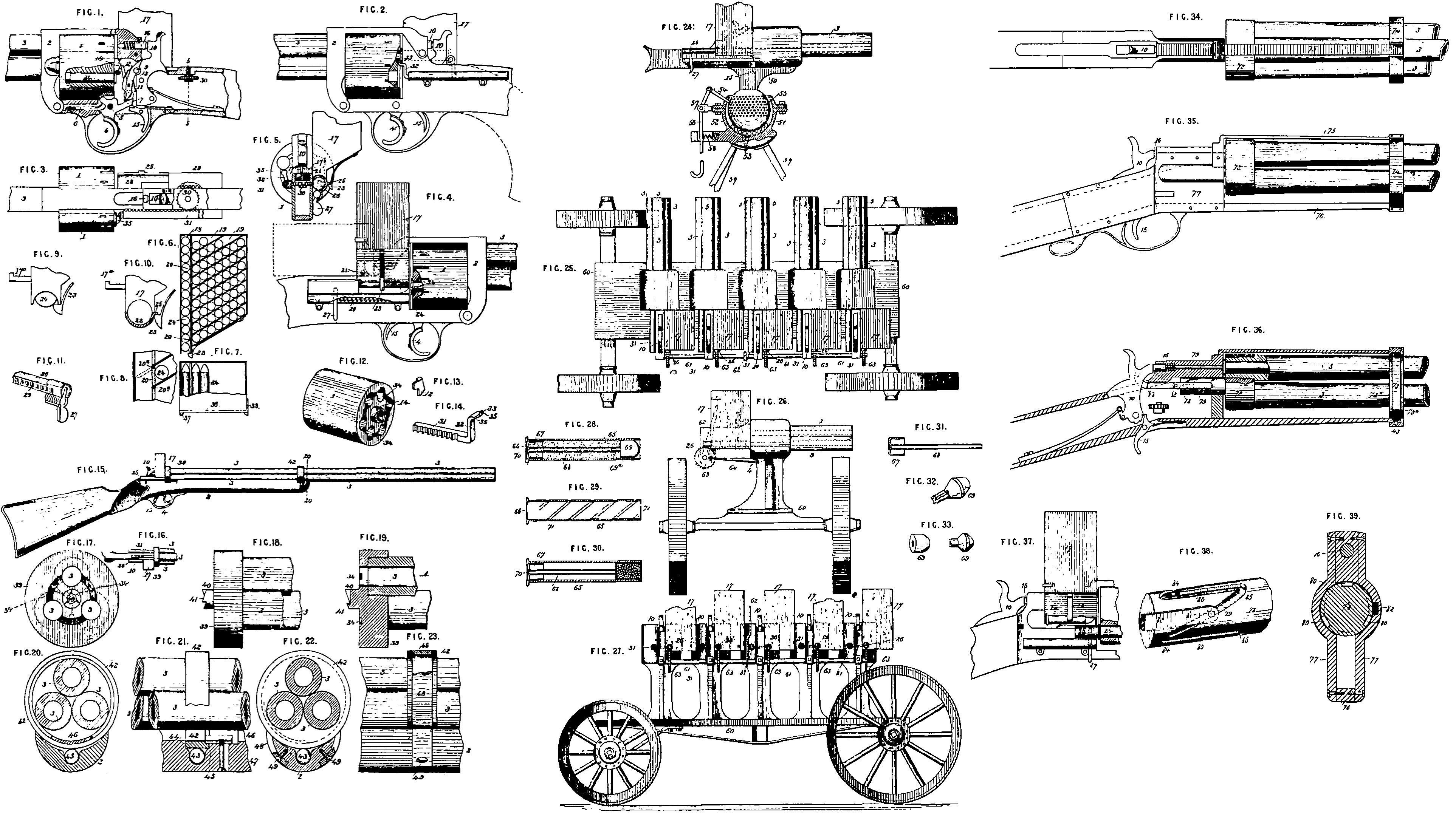
Figure 1 is a sectional side elevation showing the operating mechanism, Figure 2 is a side elevation with part of the revolving cylinder broken away to show the cartridge shell extractor. Figure 3 is a plan or top view of the operating parts. Figure 4 is an elevation of the opposite side from Figure 2 showing the magazine and its accessories. Figure 5 is a transverse section on the line 3, 5, Figure 1. Figure 6 is a vertical section of the magazine. Figure 7 is a top view of the same partly broken away, Figure 8 is a partial vertical section of the magazine on a larger scale to illustrate more clearly the construction and operation of the trap doors or valves which pass the cartridges from the reserve chambers to the feeding chamber as hereinafter described. Figure 9 is an enlarged back view of the lower end of the magazine showing tie position of the retaining spring when the magazine is in prostrate position or is detached from the gun. Figure 10 is a rear view of the same in position for use. Figure 11 is a perspective view of a portion of the charging plunger. Figure 12 is a perspective view of the revolving cylinder. Figure 13 is a detached perspective view of a dog for turning the cylinder. Figure 14 is a perspective view of the cartridge shell extractor and cylinder stop. Figures 15 to 23 inclusive illustrate a modification under which the Invention is embodied in a gun, having a cluster of barrels revolving bodily instead of a cylinder revolving in rear of a stationary barrel as in the former illustration. Figure 15 is a side elevation of the sail gun: Figure 16 is a plan of the breech portion thereof. Figure 17 is a rear elevation of the butt-ring and barrels on a larger scale. Figure 18, is a side elevation of the said butt-ring and the rear portion of the barrels. Figure 19 is a vertical longitudinal section of the same, Figure 20 is a transverse section on the line 20-20, Figure 15 looking backward. Figure 21 is a side elevation of the central portion of the barrels with their,containing ring and the front portion of the stock in section. Figures 22 and 23 are respectively a transverse section and a side elevation illustrating a modification in construction of the parts shown in Figures 20 and 21. Figure 24 is a side elevation partly in section of a portable machine gun embodying the Invention. Figure 25 is a plan of a machine battery gun embodying the Invention Figure 26 is a side view of the same. Figure 27 is a rear view thereof. Figures 28 to 33 inclusive represent an improved cartridge provided with a case of paper, thin metal or other suitable material in cylindrical form with an open front and a closed back. Within this case is inserted a saucer shaped cup having a peripheral flange to fit within the ease and employed to centre and support an axial tube which extends forward to the base of the bullet and is centred thereon. Said bullet having a solid tail to be inserted into the tube or a hollow tail or a cavity into which the tube may be inserted. The case is the full length of the cartridge, that is to say it extends forward us far as the front of the ball. The primer is placed between the open rear end of the axial tube and the interior of the imperforate back or base of the case and is ignited by the stroke of the firing pin against the outside of the case. Figure 28 is a central longitudinal section of the improved cartridge, the bullet being shown in elevation. Figure 29 is a longitudinal section of the case or shell. Figure 30 is a longitudinal section of a shot cartridge. Figure 31 is a longitudinal section of the combined tube and centreing cup, Figure 32 is a perspective view of one form of bullet. Figure 33 is a perspective view of two bullets-one with a hollow tail and the other with a hollow in its base to receive the end of the tube, Figures 34 35 and 36 are respectively a top view a side elevation and a longitudinal section omitting the loading mechanism of a gun revolved by means of spiral grooves on a projecting breech stud. Figure 37 is a side view partly in section showing the loading mechanism, Figure 38 is a perspective view of the projecting breech stud or stem on a larger scale, Figure 39 is a transverse section of the said breech stud or stem and its housing.
1 represents a revolving cylinder having any desirable number of chambers, three or more, and turning within the breech frame 2 to which is fixed the barrel 3 so that the successive chambers of the cylinder may be brought into tiring position in the rear of said barrel in customary manner. For revolving the chambered cylinder when cocking the piece a trigger 4 is shown fulcrumed at 5 and retracted by a spring 6. Said trigger is provided with a rigid arm 7 bearing on an arm 8 pivotted at 9 to a hammer 10, and thrown out by means of a spring 11, an anti-friction roller being mounted in the lower end of the arm 8, to receive the bearing of the rigid trigger arm 7. 12 represents a dog hinged to the cocking arm 8 and thrown out by a spring 13. Said dog engages with the ratchet teeth 14 in the rear of the cylinder 1 for revolving the same. The firing trigger is shown at 16 and a firing pin of common construction at 16. The improved magazine is shown at 17 and in the detailed views Figures 6, 7, and 8. It is constructed with a vertical feeding chamber 18 at one side, extending the whole height of the magazine and with a number of reserve cartridge chambers 19 having inclined fours and communicating with the vertical feeding chamber 18 through hinged trap doors 20 so that when the cartridges in the vertical feeding chamber 18 descend below the trap door of the uppermost reserve chamber 19 the said door will open either by the gravity of the cartridges in the reserve chamber. or by means of a spring and permit the reserve cartridges to slip or roll into the feeding chamber and so on with all the inclined reserve chambers successively. from the top. An automatic and continuous feed of all the cartridges in the magazine is thus effected without obstruction or choking.
This magazine may be constructed mainly of paper or of simple sheet metal and may readily be adapted to contain 60 or more cartridges. The magazine is pivotted at 21 see Figure 4; by one of its lower corners to the top of the gun stock directly in rear of the revolving cylinder 1 and in position to bring the vertical feeding chamber 18 directly over the loading trough 22. This mode of engaging the magazine admits of its being tipped back into prostrate position for the purpose of removing it from the stock.
To the inclined bottom of the magazine is fixed a spring catch 23 projecting beneath the bottom of the vertical feed chamber 18 so as to prevent the escape of cartridges when the magazine is removed from the gun or is in the prostrate position. This position of the spring catch is shown in Figure 9.
The magazine is removed from the gun by first releasing the spring catch 23 and tipping the magazine back as shown in dotted lines in Figure 4. This allows the hook 17ᵃ to pass beneath the yoke 17ᵇ which disconnects the magazine from the gun.
The cartridges are shown in the various Figures at 24.
When the magazine is erected in feeding position the spring catch 23 engages beneath a lug 25 on the side of the feeding trough 22 as illustrated in Figure 10 said spring catch being thus removed from the bottom of the magazine and serving to hold the magazine in place while permitting the cartridges to feed successively into the trough 22.
The bottom cartridge is now directly in front of the charging plunger 26, the construction of which is shown in the detached view Figure 11. It is provided with a downwardly projecting handle 27 and is retracted by a spring 28. On its inner side is formed a rack 29 Figure 11 gearing with a pinion 30 Figures 1, 3 and 5 the opposite side of which meshes with the sliding stem or stock of the cartridge extractor 31. This is formed in front with an upwardly projecting rigid arm 32 terminating in a hook 33 which fits in an annular groove 34 extending around the rear face of the cylinder 1 in a circle coincident with the centres of the charge chambers. The hook 33 is flanked by shoulders 35 which rest against the rear face of the revolving cylinder and limit the penetration of the hook 33 into the groove 34 and serve also by contact with the-projecting flanged bases of the cartridge shells to arrest the rotation of the cylinder at the proper points for firing.
The hook 33 at the same time engages beneath the flanged cartridge shell in readiness for drawing out the said shell when the extractor 31, 32, 33, is retracted by the movement of the loading plunger 26 as before described.
The cartridges are introduced into the magazine 17, from the rear; a door 36, for this purpose being shown in Figure 17, hinged at 37 and held in closed position by a catch 38.
The opening of this door exposes all the chambers 18 and 19 simultaneously.
For the purpose of illustration a six chambered cylinder is shown, A modified form of cylinder may be used with but three chambers. If preferred the cylinder may turn on a fixed pintle and may be rotated by teeth or notches in its periphery according to another well known mode.
In Figures 15 to 28, three barrels 3, 3, 3, are shown in a connected revolving cluster instead of a revolving cylinder with a stationary barrel.
These barrels are secured together at their rear ends by being screwed into a revolving breech ring or band 39; said band being provided with a pivot 40, on which the barrels turn and having notches 41, for the revolution of the barrels by the means already described, Located at a convenient point on the barrels so that they may be as nearly balanced between the butt and muzzle as practicable is a second ring 42, to hold the barrels firmly together and also to hold them in position in the stock 2. The ring rests and turns on an anti-friction ball 43 and bears backward against a shoulder 44 in the stock 2, and in front against a shoulder 45 of less depth; being confined in the seat thus provided by a sliding segmental catch 46 secured by a screw 47, the said catch 46 fitting within the annular groove in the forward edge of the ring 42 so as to permit the free rotation of said ring together with the barrels as already described.
In the modified construction shown in Figures 22 and 23 a band 48 is employed passing either partially or entirely around the barrels and stock and secured to the stock by any suitable means as for example by screws 49, the said band fitting within a peripheral groove in the ring 42 as clearly shown in Figures 22 andZ. 23 and the ball 43 being used as before.
The loading magazine and plunger and the cartridge extractor are used as before described the rear face of the butt ring 39 being provided with the annular groove 34 to receive the hook 33 of the cartridge extractor and permit it to take an effective grip upon the flange of the shell which is presented to it.
By a gun of this construction, lightness will be obtained as the barrels are separate and distinct from each other and yet held firmly together by means of the rings or bands 39 and 42.
In Figure 24 the gun is shown mounted by a pedestal 50 and ball 51 on a stand which may have the tripod form here represented. The ball 51 rests on a number of small antifriction balls 53 and is contained in a socket 52 so as to form a universal joint and is held in any position to which it may be set by a pin 54 engaging in any one of the numerous holes 55 provided for the purpose on the: surface of the ball 51.
The pin 54 is retracted by a lever 56 fulcrumed at 57 and operated either by the hand or foot, n spring 58 being employed to press the lever 56 outward and thus cause the pin 54 to engage with either of the holes 55 which nay come in line with it. This device admits of the ready adjustment of the gun either for elevation or training. If desired a more delicate adjustment for training may be added by pivotting the pedestal or standard 50 within the ball 51 and training: by a horizontal set screw or screws in a well known manner.
The gun 52 is shown supported on hinged legs 59, but may be mounted on a saddle or any other support if preferred.
In Figures 25, 26 and 27 is shown a machine battery gun adapted for prolonged? and rapid tire having a number of the multiple revolving barrels 3 mounted in a horizontal range. Any desirable number of these cluster of barrels are supported on a suitable carriage 60 and revolved simultaneously by a transverse shaft 61 operated by a hand lever 62 and carrying pinions 63 from each of which a connecting rod 64 extends to the trigger 4 which revolves each cluster of barrels and cocks the hammer thereof.
The pinions 63 on the shaft 61 gear with racks on the loading plungers 26 which impart the simultaneous movement to the cartridge extracting device in the manner already described in reference to small arms.
The barrels may be fired successively by mechanism similar to that described in English Patent No. 5459 of 1880 or by a simple attachment to the trigger by which they will be operated by the loading plungers at the termination of their forward strokes. Or by mechanism similar to that in a self cocking pistol which releases the hammer at the end of the cocking action or by any other suitable means.
The three barrels of the gun shown in Figures 34, 35, 36 are secured together at their butt ends in a suitable breech piece 722 and at their forward part in a ring 73 which is held in an outer ring 74 by means of shoulders 739, the outer ring being grooved and made in halves and fastened by screws to longitudinal reach pieces or bars 75 76 The lower reach bar 76 bas in its forward end two pockets for the reception of the friction balls 43. These reach pieces extend backward and are secured to the stock by the usual means employed. Now to securely hold these bars in place, I employ two side plates 77, extending from the breech of the barrels back and surrounding the stock and secured in place by means of screws near the top and bottom. Between the plates 77 the lock and turning mechanism are located, the hammer trigger and main spring being of the usual form. Now to turn the barrels the following means are employed.
The breech piece into which the barrels are screwed has a stem or stud 78 which has bearing between the side plates, said stem has on its periphery three spiral grooves 79, connected by straight longitudinal grooves 80, Fitting into said grooves is a pin 81 secured to a slide 2 which works in a groove or guide upon the inside of one of the side plates 77 and is connected to the hammer by means of a link 83, said link having an offset or shoulder of sufficient depth to bring it in line with the centre of the hammer, The cocking of the hammer is thus caused to turn the barrels by the pin 81 travelling in one of the spiral grooves 79. At the end of said grooves are small spring switches 84 behind which the pin passes, so that when the hammer falls, the pin will travel in one of the straight grooves 80, to the opposite end when it passes under another spring switch 85 and locks the barrels so that they cannot turn without the elevation of the hammer, and also prevents the pin traveling in any groove other than the one desired by the required movement of the hammer.
The charger and extractor are substantially the same as already described but the hand bold of the stock is enlarged sufficiently to allow the rack to travel back into the stock, and to the rear of the charger rack is attached a pull-spring which is also located in the stuck and to allow of this, the side plates have openings through which said racks pass.
The charging plunger is of the form shown in Figure 37 having a small plunger 86 attached to one end of the rack. On top of said plunger is attached 4 spring of about ½, the length of the cartridge and bent down at the rear end so as to pass freely under the flange of the cartridge above it upon the return stroke. This also passes into the stock through an opening in the side plate. The lower side of the pocket into which the cartridge falls is slotted to allow the thumb piece to travel back and forth.
The pinion connecting the charger and extractor is located as hereinbefore described.
The guide for the extractor rack extends so far forward as to freely admit of the cartridge shell being withdrawn.
The outer case 65 of the cartridge (Figures 28, 29 and 30) may be made of paper thin metal or other suitable material with an open front and a closed and imperforate base 66. Inserted in the shell or case from the front is a saucer shaped cup 67, the flanged periphery whereof fits within the interior of the case and serves to centre and secure the rear end of the central tube 68, the front end of which receives the central tail 699 of the bullet 69. The case 65 is made of sufficient length to extend to the front of the bullet 69, so that the shell after discharge of the bullet will be of the same length as the loaded cartridge. This enables the use of the empty shell as a gauge in feeding the cartridges into the revolving or sliding breech of the gun (as the case may be) from suitable magazines either from the front or rear. For rear loading the cartridge is made with the customary base flange.
In constructing the cartridge the connected cup 67 and tube 68 are inserted within the case 65 with a primer 70 of any preferred form in position beneath the end of the tube and between it and the interior of the base 66.. The cup and tube may be made in one piece or may be separate and secured together by fitting the. end of the tube within or on the outside of a central collar on the cup. The primer 70 may be of disc form and set in a cavity as shown or may be of cap form and fitted on a nipple on the rear extremity of the tube GS. The tube 68 and the case 65 around it} are both filled with powder and the tail 692 of the bullet fitted within the end of the tube or as shown in Figure 28 the tail of the ball or the base of the ball itself may be made hollow to receive the end of the tube. When the tail of the ball is made solid it preferably has the form (in section) of a St. Andrew’s cross as illustrated in Figure 32 which is highly advantageous in improving the range and accuracy in Hight. The stroke of the firing in being delivered on the centre of the base 66 acts through the thin material of the case on the primer 70 within which is seated on the end of the tube 68, while the latter is seated against the base of the ball 69 so as to provide a rigid and efficient anvil to support the primer under the blow and insure its ignition. The tube may be without perforations so that the powder within it will be first burned and the main body of powder will then be ignited from the front or the tube may be perforated so as to ignite the entire body as promptly as possible.
The improved cartridge may be made cither with or without a flanged base, as preferred: The Invention is applicable alike to military and sporting guns and may be applied to a shot cartridge as illustrated in Figure 30.
Especially for cannon it is found desirable to fur the case with spiral or other ribs as illustrated at 71, in Figure 29 which afford a cushion in the first explosion of the charge and hence avoid violence to the gun.
Having thus described the nature of the said Invention and the mode in which the same is carried into effect I would have it understood that what I claim is
First. A revolving cylinder or barrel having three or more load chambers in combination with a loading plunger and cartridge extractor operated by a simultaneous movement substantially as herein described.
Second. The combination of the self feeding magazine 17, plunger 26 loading handle 27 retracting spring 28 rack 29, pinion 30, and extractor 31, substantially as and for the purposes set forth.
Third. In a revolving fire arm a sliding catch serving the combined purposes of stopping the revolving barrel or cylinder in firing position and extracting the empty shell.
Fourth. A revolving chambered cylinder formed with a groove extending around or partially around its base in combination with a cartridge shell extractor having a hook engaging in said groove so as to be conducted to its effective position in front of the flange and with a shoulder serving by contact of the base of the cartridge to stop the cylinder in firing position.
Fifth. The combination of a revolving chambered cylinder with an automatic feed magazine and reciprocating loading mechanism constituted substantially as herein described.
Sixth. A magazine consisting of a vertical feeding chamber and a number of lateral reserve chambers or receptacles communicating therewith so as to supply fresh cartridges to it automatically when the first chamber is depleted.
Seventh. The combination of the vertical feeding chamber the lateral reservoirs or supply chambers and the hinged flaps or doors for permitting the passage of cartridges from the supply chambers to the feed chamber when the latter is depleted substantially as described.
Eighth. The combination of the tilting magazine 17 spring catch 23 trough 22 and lug 25 constructed and operating as set forth.
Ninth. A machine battery gun constructed with a horizontal range of clustered revolving barrels and with loading and shell extracting mechanism substantially as set forth.
Tenth, The combination of the range of barrels 3 shafts 61 gearing 63 magazines 17 and loading plungers 26 substantially as herein shown and described.
Eleventh. The combination of the range of barrels 3 loading plungers 26 shell extractors 31 and connecting pinions 30 constructed and operating substantially as herein shown and described.
Twelfth. A gun constructed with a connected cluster of barrels and a stud or stem projecting rigidly therefrom spirally grooved to effect the rotation of said cluster of barrels by the action of a toothed slide substantially as described.
Thirteenth. The combination of the revolving barrels 3 projecting spirally grooved stem 78 toothed slide 82 hammer 10 and connecting link 83 substantially as and for the purposes set-forth.
Fourteenth. The combination of the cluster of barrels 3 the shouldered ring or band 73 within which they are secured the outer guide ring or band 74 and the reach bars 75, 76, substantially as and for the purposes set forth.
Fifteenth. A cartridge constructed substantially as herein described whether for large or small arms.
In witness whereof I the said Benjamin Joseph Barnard Mills have hereunto set my hand and seal this Twenty first day of June in the year of our Lord One thousand eight hundred and eighty two.
B. J. B. MILLS. (L.S.)