
Britain 2731
A.D. 1882, 10 June, № 2731.
Revolvers or Pocket Pistols.
LETTERS PATENT to Edward Griffith Brewer of 33 Chancery Lane in the County of Middlesex for an invention of “Improvements in revolvers or pocket pistols” Communicated to him from abroad by Jacques Edmond Turbiaux of Paris France
PROVISIONAL SPECIFICATION left by the said Edward Griffith Brewer at the Office of the Commissioners of Patents on the 10th June 1882.
Edward Griffith Brewer of 33 Chancery Lane in the County of Middlesex “Improvements in revolvers or pocket pistols” (A Communication to me from abroad by Jacques Edmond Turbiaux of Paris France)
These improvements relate to revolvers or pocket pistols.
It is well known that many systems of pocket revolvers are in existence but they are inconvenient for holding in the hand which ought to be one of the first conditions of a good arm of this class. Besides only a limited number of shots can be fired on account of their small size, it follows that the arm becomes dangerous to the person using same because if the adversary seizes the hand of the person having the revolver the adversary becomes the stronger and can snatch away the arm with much greater facility as it can only be held by the two fingers, If to avoid these inconveniences a revolver is made which can be well held in the hand the size becomes too great, heavy and cumbersome to carry in the pocket. By the inventor has obviated the inconveniences above indicated. It differs completely in form, simplicity and strength from anything of the kind invented up to the present day. Its size is about that of an ordinary watch, the number of charges it carries may be varied; for example I propose to describe the invention with reference to a revolver capable of carrying ten charges, central fire cartridge, rifled barrel and long range considering its restricted size but it should be understood that the number of projectiles employed may be varied and central or ring fire or other cartridges may be used. This arm may be put in the waistcoat pocket as easily as a watch and without being inconvenient: it is held: entirely within the hand the barrel end only passing the fingers; it is thus well held in the hand and it is next to impossible to pull it away. It can be used as a “knuckle duster” a terrible weapon protruding between the fingers and available when the ammunition bas been expended.
The foregoing improvements have been arrived at by the following arrangements
1. By dispensing with the ordinary stock or handle.
2. By making use of or employing a flat drum or breech of modified construction to that at present in use.
3. By boring centrally the breech.
4. By employing very simple mechanism placed within the case forming the bottom of the box which encloses the whole.
According to one arrangement a box is employed which may be made of cast iron, steel or other suitable metal provided with two ears or projections acting as holding pieces for the fingers; at the opposite end.of the box there is a hinged piece which operates rods passing through slots in the box; one of these rods communicates motion to the striker and the other imparts the necessary motion to the breech piece; this rod is composed of a rigid portion which slides in a groove. formed in the box and of a flexible or spring portion which enters at a given time into the breech slot to cause it to turn which is arrested when pressure is removed from this hinged piece. When the box is taken in the hand the ears or projecting pieces before referred to being taken as holding points or supports the hinged piece at bottom being compressed the lever in connection therewith operates the tumbler of the striker and at a certain part of its course the end of this lever abuts on the tumbler, and causes the striker to oscillate but the end of the lever is freed from the tumbler aided by a ring but a spring fixed at one point is always engaged with the tumbler so that as soon as the upper end of the lever escapes from the tumbler the spring will act on the striker and will make it strike sharply and vigorously on the fulminate of the projectile, a small spring will bring the lever back
The breech piece is of special construction it may be of steel or of any other metal and of a truncated cone shape; it has on its circumference as many cartridge chambers as the same will admit of, recesses being provided for retaining the rings of the cartridges in position; between each chamber and on the flat of the breech a second recess of hooked form serves to push the breech a division for each shot fired but that is not sufficient for preserving the perfect parallelism of the chamber with the barrel if the precaution is riot taken to form on the circumference of the said breech some V shaped notches as hereafter more fully referred to. The shutter or hinged piece carries or is provided with a spring which abuts on a spring ear piece fixed to the box the shape of which corresponds to that of the V shaped notch formed in the breech block. Supposing the revolver to be in a state of rest the spring above the shutter only rests on the ear piece which will be engaged in the V shaped groove formed in the breech but as soon as the shutter is pressed the spring rod causes the breech to turn by acting on the recesses owing to the shape of the V grooves of the breech and of the ear piece the latter yielding to allow the breech to turn. According to the degree of compression given to the shutter or hinged piece a graduated pressure will be exerted; during the first period the breech will be operated and will turn on its axis but this first period passed the pressure of the spring will increase and compress the ear piece into the V shaped notch before the escape of the striker, this is very important because it is necessary that the cartridge chamber always comes opposite the barrel before the percussion can be effected. A ring or eye is connected to the arm for attaching same to a chain of watch or otherwise. All the mechanism being carried in the box the said box may be covered in any convenient manner, pivotted on an axis for example or retained or fixed by bayonet attachment or screw and which can be with facility opened.
The truncated shape of the ring breech is important to be able to disengage it with facility because if it were perfectly cylindrical externally and internally it would be difficult to get out. A stop is or may be placed on the box so that by pushing it in one direction the: effect of the shutter or hinge would be annulled; by pushing it the other way it would be free to act.
According to a modification the centre of the joint of the shutter or hinged piece is further from the box and the said hinged piece is concentric to the said box instead of being eccentric. Instead of as in the previous arrangements taking the fingers on the upper part and exerting pressure with the palm of the hand on the shutter or hinged piece according to a modification the point of support is taken at the lower part with the palm of the hand and the fingers act on the eat pieces which are made movable and are provided with cylinder sliding on the barrel and a helical spring brings the cylinder to its natural position when no more pressure is exerted on the hand. The principle is the same as the preceding but the mode of carrying out same somewhat different.
After having removed the cover which may be fixed by hinge or pivot or joint the revolver can be turned until the breech which is conical for this purpose falls into the hand, the cartridges are then introduced by the centre, the breech is replaced in position the cover is closed, then having withdrawn the safety catch the arm is ready for operation
Where the use of the hinged shutter is dispensed with by employing the bottom of the arm as the fulcrum and the fingers for regulating or for operating the movement in one or the other case it is always by the action or position of the hand that the arm is fired.
The faces of these fire arms may be covered with plates of wood or metal ornamented, gilded or silvered nickeled or engraved or otherwise.
SPECIFICATION in pursuance of the conditions of the Letters Patent filed by the said Edward Griffith Brewer in the Great Seal Patent Office on the 9th December 1882.
Edward Griffith Brewer of 33 Chancery Lane in the County of Middlesex “Improvements in revolvers or pocket pistols” (A Communication to me from abroad by Jacques Edmond Turbiaux of Paris France)
These improvements relate to revolvers or pocket pistols. It is well known that many systems of pocket revolvers are in existence but they are inconvenient for holding in the hand which ought to be one of the first conditions of a good arm of this class, Besides only a limited number of shots can be fired on account of their small size; it follows that the arm becomes dangerous to the person using same because if the adversary seizes the hand of the person having the revolver the adversary becomes the stronger and can snatch away the arm with much greater facility as it can only. be held by the two fingers. If to avoid these inconveniences a revolver is made which can be well held in the hand the size becomes too great, heavy and cumbersome to carry in the pocket.
By the construction of the revolver forming the subject matter of this Invention, the inventor has obviated the inconveniences above indicated. It differs completely in form, simplicity and strength from anything of the kind invented up to the present day. Its size is about that of an ordinary watch, the number of charges it carries may be varied, for example I propose to describe the invention with reference to a revolver capable of carrying ten charges, central fire cartridge, rifled barrel and long range considering its restricted size, but it should be understood that the number of projectiles employed may be varied and central or ring fire or other cartridge may be used, and of varying calibres. This arm may be put in the waistcoat pocket-as easily as a watch and without being inconvenient; it is held entirely within the hand the barrel end only passing the fingers; it is thus well held in the hand and it is next to impossible to pull it away, It can be used as a “knuckle duster” a terrible weapon protruding between the fingers and available when the ammunition has been expended.
The foregoing improvements have been arrived at by the following arrangements.
1. By dispensing with the ordinary stock or handle.
2. By making use of or employing a flat drum or breech of modified construction to that at present in use.
3. By boring centrally the breech.
4. By employing very simple mechanism placed within the case forming the bottom of the box which encloses the whole.
And in order to more fully explain the Invention I will now describe the same with reference to the accompanying drawings.
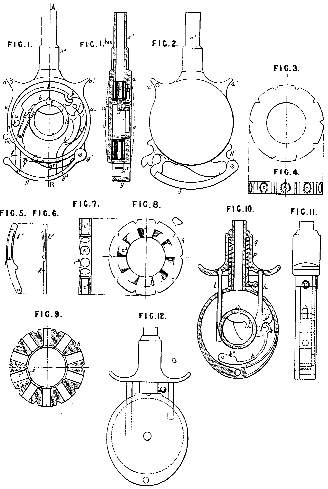
Figure 1 illustrates one arrangement of revolver or pocket pistol made according to this Invention, Figure 1ᵇⁱˢ is a vertical section through A B Figure 1.
According to this arrangement a box a is employed which may be made of bronze, steel or any other, suitable metal, it is provided at its upper part with a barrel a² or a socket screw threaded inside so that barrels of different lengths may be screwed in when necessary; on each side of the barrel on the box there are two ears or projections a¹ a¹ acting as holding pieces for the fingers. At or about the middle of the said box a fixed ring serves as a breech piece and is provided with an opening centrally and on the barrel axis for the passage of the striker; at g¹ on the box a there is a hinged piece on which the trigger or operating lever g is mounted. Two slots are formed in the bottom of the box a for the passage of the two rods h and l. The rod h communicates motion to the striker and the spring rod l shown detached at Figures 5 and 6 imparts the necessary motion to the magazine b; it will be seen that this rod is composed of a curved rigid portion which slides in a groove also curved, formed in the bottom of the box and of a flexible or spring portion l¹ which enters at a given time into the notches e³ of the magazine to cause it to turn which is arrested when pressure is removed from this hinged trigger or operating piece g. “Striker”;— When the box a is taken in the hand the ears or projecting pieces a¹ before referred to being taken as holding points or supports the hinged piece or trigger or operating lever g is compressed, the lever h moves the cam j¹ which carries at its other end a piece of a lancet shape or trigger which works inside the breech ring and carries the striker; the end 4 of the lever h in connection therewith operates the cam j¹ of the striker and at a certain part of its course the end i of this lever abuts on the cam j¹ and causes the striker to oscillate but the end i of the lever is freed from the cam j¹ aided by the point h¹¹¹ but a spring k fixed at one point k¹¹ will always keep its end k¹ engaged with the cam so that as soon as the part i of the lever escapes from the cam the spring k will act on the striker and will make it strike sharply and vigorously on the fulminate of the projectile whether it be central or ring or other fire cartridge. A small spring h¹ will bring the lever h back to engage the cam j¹ according as the hinged piece g assumes its first position by the action of the spring g²
The cartridge magazine is shown detached at Figures 3, 4, 7, 8 and 9. This magazine b is of special construction it may be of steel or of any other metal and preferably of a truncated cone shape; it has on-its circumference as many cartridge chambers e¹ as the same will admit of; recesses c² being provided for retaining the rings of the cartridges in position; between each chamber and on the flat of the magazine a second recess e³ of ratchet form serves to push the magazine a division for each shot fired but that is not sufficient for preserving the perfect parallelism of the magazine with the barrel if the precaution is not taken to form on the circumference of the said magazine some V shaped notches as hereafter more fully referred to
The operation of the magazine Figure 1 is as follows:
The hinged lever g carries or is provided with a spring g² which abuts on a spring ear piece n fixed to the box, the shape of which corresponds to that of the V shaped notched formed in the periphery of the magazine. Supposing the revolver to be in the position represented at Figure 1 that is in a state of rest, the spring g² above the hinged lever g only rests on the ear piece n which will be engaged in the V shaped groove formed in the magazine, but as soon as pressure is put on the hinged lever the spring rod J causes the magazine to turn by acting on the recesses e³ owing to the shape of the V grooves of the magazine and of the ear piece n the latter yielding to allow the magazine to turn. According to the degree of compression given to the hinged lever g a graduated pressure will be exerted; during the first period the magazine will be operated and will turn on its axis, but this first period passed the pressure of the spring g² will increase and compress the ear piece n into the V shaped notch before the escape of the striker; this is very important because it is necessary that the magazine always comes opposite the barrel before the percussion can be effected. A ring or eye a³ is connected to the arm for attaching same to a chain of watch or otherwise. All the mechanism being carried in the box a the said box may be covered in any convenient manner, pivotted on an axis for example or retained or fixed by bayonet attachment or screw and which can be with facility opened.
The truncated shape of the magazine is important to be able to disengage it with facility because if it were perfectly cylindrical externally and internally it would be difficult to get out. A bolt m is or may be placed on the box a so that by pushing it in one direction the effect of the hinged lever would be annuled; by pushing it the other way it would be free to act. Between the hinged lever g and its abutment there is sufficient play allowed for the striker to facilitate the action of the magazine.
Figure 2 is a view of a revolver constructed according to this Invention of a somewhat modified form.
According to this modification the centre of the joint of the hinged lever is further from the box a and the said hinged piece is concentric to the said box instead of being eccentric, it is thought unnecessary to re-produce the mechanism which is similar
Figures 10,11 and 12 are views in vertical section, side elevation and front elevation of a somewhat modified arrangement and although of an appearance completely different it is in construction quite similar to the arrangement shown at Figure 1, the principle is always the same and to make it still clearer the same letters of reference in both cases are preserved.
Instead of as in the previous arrangements, taking the fingers on the upper part and exerting pressure with the palm of the hand on the shutter or hinged piece according to this modification the point of support is taken at the lower part with the palm of the hand and the fingers act on the ear pieces which are made movable on the barrel, and a helical spring g brings the cylinder p to its natural position when no more pressure is exerted on the hand. The principle is the same as the-preceding but the mode of carrying out same somewhat different.
WORKING OF THE REVOLVER.
After having pushed aside the stop bolt that is from the side of the hinged piece and removed the cover which may be fixed by hinge or pivot or joint the revolver can be turned until the magazine, which is conical for this purpose falls into the hand, the cartridges are then introduced by the centre, the magazine is replaced in position, the cover is closed then having withdrawn the safety catch the arm is ready for operation.
The hinged lever at the bottom of the box might be dispensed with in which case the bottom of the box itself forms the point of support and the fingers for regulating the action. In either case it is by closing the hand that the arm is discharged.
The faces of these fire-arms may be covered with plates of wood or metal ornamented, gilded or silvered nickeled or engraved or otherwise as shown by the dotted lines at Figure 1ᵇⁱˢ, by this means these weapons may be very highly decorated when desired, the engraving silvering or other decoration may be made directly onto the box itself.
The inventor calls this arm “The Protector.”
Having now described the nature of the said Invention and in what manner the same is to be performed I declare that I Claim:
First: In pocket pistols or revolvers, the construction and employment of same without the butt end substantially as and for the purposes set forth.
Second: The employment of the striker in the hollowed out portion and the centre of the magazine and utilizing the bottom of the box as a medium for operating the parts all substantially as set forth.
Third: The construction and arrangement of the parts whereby the arm can be taken in the palm of the hand as the fulcrum or supporting point pressing it on the hinged lever or by taking the supporting point in the hand and pressing with one of the fingers all substantially as and for the purposes set forth.
Fourth: The construction and employment of revolvers or fire-arms which are held in the hand with nothing exposed to view except the barrel all constructed and operated substantially as and for the purposes set forth.
In witness whereof I the said Edward Griffith Brewer have hereunto set my hand and seal this Eighth day of December in the year of our Lord One thousand eight hundred and eighty two:
E G BREWER (L.S.)