
US 447219
UNITED STATES PATENT OFFICE.
CHARLES A. WEEKS AND CHARLES FOEHL, OF PHILADELPHIA, PENNSYLVANIA.
LOCK FOR REVOLVERS.
SPECIFICATION forming part of Letters Patent No. 447,219, dated February 24, 1891.
Application filed March 4, 1890. Serial No. 347,357. (No model.)
To all whom it may concern:
Be it known that we, CHARLES A. WEEKS and CHARLES FOEHL, of Philadelphia, in the county of Philadelphia and State of Pennsylvania, have invented a new and useful Improvement in Fire-Arms; and we do hereby declare that the following is a full, clear, and exact description of the same.
Our invention relates to pistols.
It consists of two parts, both applicable to the same kind of pistol. The first part is an improvement in the retracting-spring of the firing-pin and the second an improvement in
the rebounding mechanism.
Our said invention is illustrated in the accompanying drawings, in which—
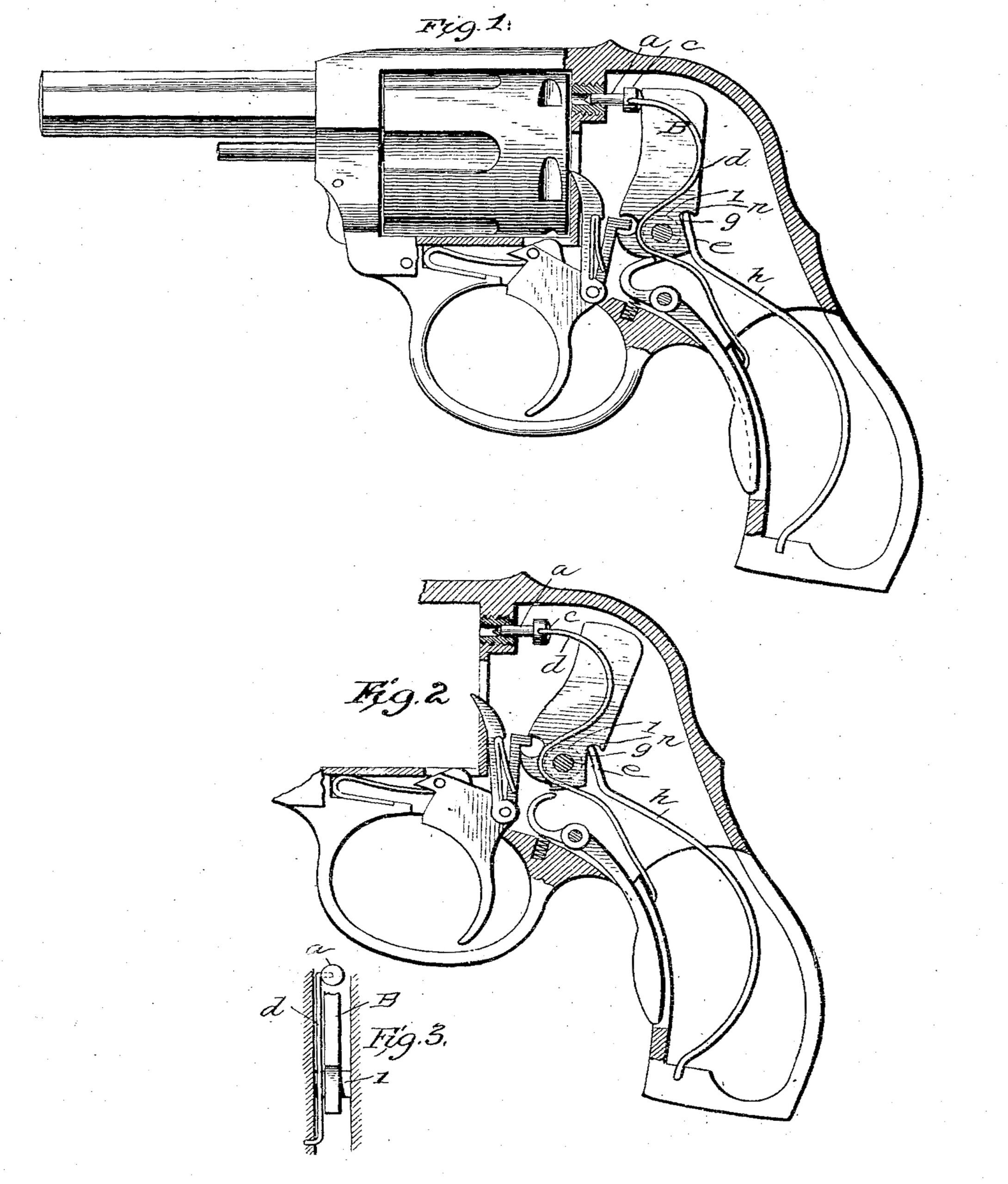
Figure 1 represents a pistol in side elevation with the side of the casing and grip
broken away. Fig. 2 represents the hammer drawn back nearly to the firing-point. Fig. 3 is a section showing the position of the spring which retracts the firing-pin.
In the drawings the firing-pin is shown at a. Heretofore such pins have been placed in a rabbeted or shouldered cavity; made large enough to receive a coiled spring surrounding the pin and placed between a flange on the pin and a shoulder about the bottom of the cavity, or such pins have been connected to the hammer, so as to be held back by the hammer when at half or safety cock. By a simple construction we avoid the rabbeting of the cavity for the firing-pin, and hold the pin in place independently of the hammer by means of a spring arranged outside the firing-pin, attached thereto, and adapted to draw the pin back upon rebound of the hammer. The particular form of the spring is not material, provided it be arranged to operate under conditions just above specified; but we have shown a simple, economical, and practicable form. This consists of a spring of bent wire. The orifice for the firing-pin is a plain hole through the breech-piece, and the firing-pin is a simple pin a, substantially cylindrical and having a point and a head c. The head has a lateral hole, which receives the laterally-bent end of the retracting-spring d. This spring has a sinusoidal curve extending downward in an arm, which bears against a boss on the wall of the chamber, and at the end is bent laterally and enters a hole in said wall. The spring bears against the boss l, (shown in dotted lines,) and is held in place thereby and by its connections at the ends, as before explained. It also holds in place the firing-pin and retracts it as the hammer is drawn back to the half or safety cock, but yields when the hammer falls. The spring is simply a bent wire of steel. The pin is a plain pin, and the parts mutually support each other without direct connection of the pin with the hammer.
Our special construction of the rebounding mechanism involves a reduction of the number of parts. The hammer B is pivoted on a pin e, which passes through the bosses l l on the inner faces of the walls of the cavity, the hammer being supported between these bosses, leaving a space on each side for the spring, one of the bosses supporting the spring as above explained. The hammer is provided with means, as shown, for cocking and firing, as shown in the patent of Foehl, No. 417,672, dated December 17, 1889; but the invention in neither part is confined to this special form.
The rear and lower edge of the hammer is cut away, as shown, in the form of a rabbet g. This rabbet extends above and below the pivot of the hammer and is inclined to correspond to the direction of the mainspring h. The upper part of the rabbet is undercut to form a groove n, in which rests the plain end of the spring. The end is made somewhat thinner than the groove, so as to have some motion therein. When the hammer is drawn back, the end of the spring bears in the groove and above the pivot. When the hammer has reached its extreme forward limit in firing, the lower part of the rabbet below the pivot bears on the spring, and the leverage is therefore in opposite direction, and this is sufficient to give the necessary rebound. The movement of the end of the spring in the groove is sufficient for this rebound movement.
We claim as our invention—
1. In combination, the hammer, the normally-retracted firing-pin, and means for retracting said pin and holding its rear end in position, consisting of a spring connected at one end to the pin and at the other end to the frame.
2. The hammer supported on its pivot between bosses, the firing-pin, and the spring
arranged by the side of the hammer, extending past the bosses, and connected to the pin, substantially as described.
In testimony whereof we have signed our names to this specification in the presence of two subscribing witnesses.
CHAS. A. WEEKS,
CHARLES FOEHE.
Witnesses:
FRANK SCHMIDT,
HARRY J. FRANZ.