
US 436062
UNITED STATES PATENT OFFICE.
JOHN F. MANAHAN, OF LOWELL, MASSACHUSETTS.
SAFETY-CATCH FOR FIRE-ARMS.
SPECIFICATION forming part of Letters Patent No. 436,062, dated September 9, 1890.
Application filed May 17, 1890, Serial No. 362,140, (No model.)
To all whom it may concern:
Be it known that I, JOHN F. MANAHAN, of the city of Lowell, in the State of Massachusetts, have invented a new and useful Improvement in Fire-Arms, of which the following is a specification.
My invention is intended to provide an efficient, ready, and convenient means for preventing the accidental or inadvertent discharge of fire-arms. To this end I combine with the usual lock-mechanism an independent stop-lock, whereby the hammer can be securely held against movement. I am aware that this, broadly considered, is not new with me. In most cases, however, of which I have knowledge the device for locking the hammer is spring-pressed into a position in which it normally engages and locks the hammer against any cocking movement, and is operated against the stress of its spring by hand pressure (exerted upon a knob or protuberance at some convenient point upon the handle or grip of the fire-arm) to move out of locking position; but the moment the hand pressure is removed, relaxed, or not exerted properly the locking device at once and automatically returns into locking position with respect to the hammer. It has also been proposed to move the locking device by hand in both directions—that is to say, into and out of locking position with respect to the hammer; but in this case no means were provided for assuring the retention of said device in either one of these two positions, so that there would be constant liability of the accidental shifting of the device, thus rendering its action uncertain and materially impairing its efficiency for the particular use for which it was designed.
The independent stop-lock which I have devised comprises, essentially, the combination, with the usual lock mechanism, of a dog or locking device proper, a thumb-piece or slide on the exterior of the handle, by moving which to one of the two positions it can assume the locking device will be thrown into or out of engaging position with respect to the hammer, as the case may be, and a spring-detent by which the locking device will be held against accidental movement whenever it is once brought into either one of its two positions. The thumb-piece or slide can be located. at various points on the handle, as may be found most convenient. In applying the device to revolvers or the like I prefer to locate the slide just back of the trigger-guard on that portion of the handle which faces the guard. When thus placed, it is out of the way and not liable to be accidentally operated, while it is in a position to be conveniently manipulated.
The nature of my improvement will be readily understood by reference to the accompanying drawings, in which I have represented the invention in its preferred form as applied to a revolver.
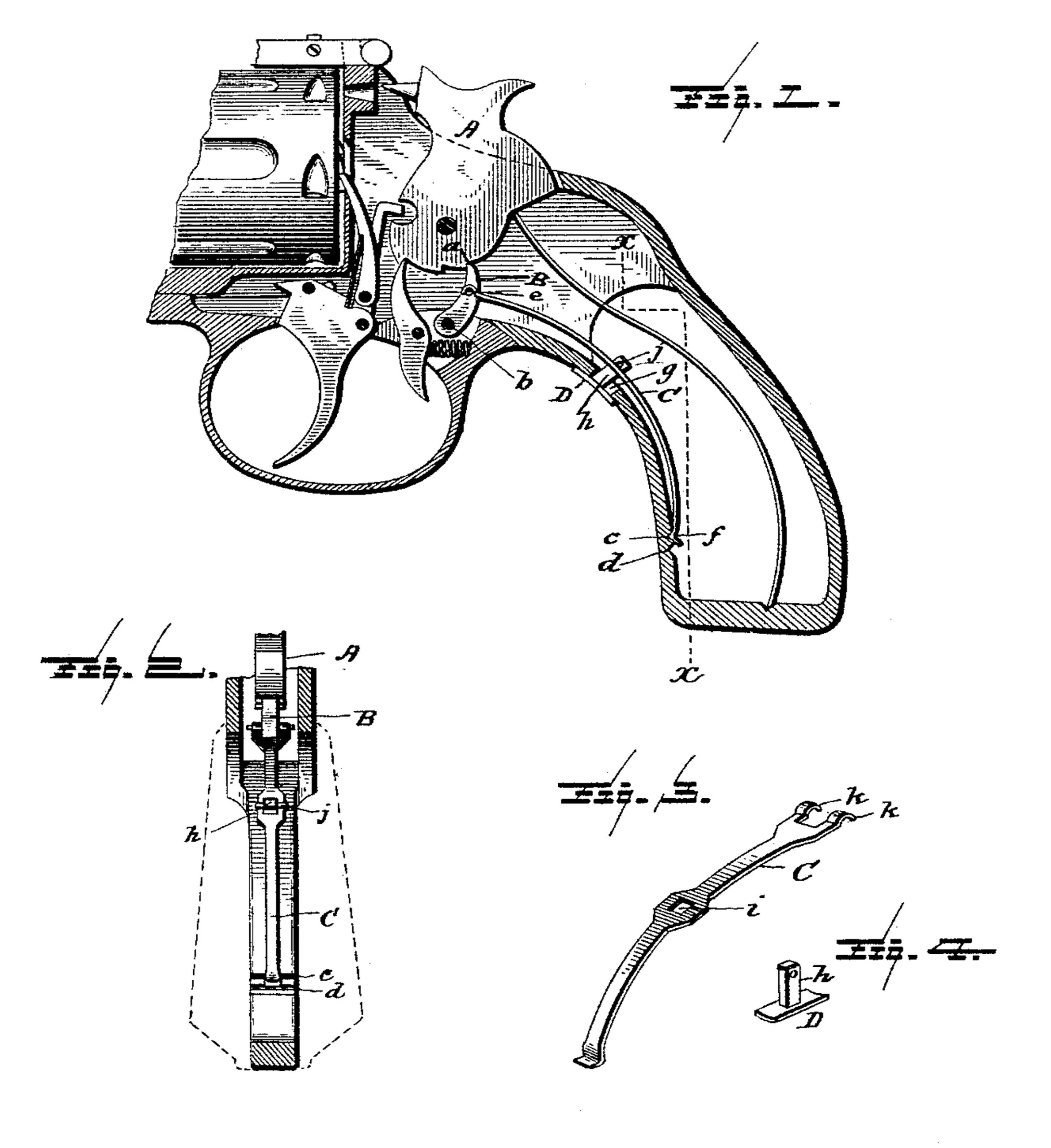
Figure 1 is a longitudinal vertical central section of so much of a revolver as needed for the purposes of explanation. Fig. 2 is a rear sectional elevation of the handle on line x x, Fig. 1. Figs. 3 and 4 are views of parts of the stop-lock, hereinafter more particularly referred to.
The revolver shown in the drawings is of the Harrington & Richardson make, now in the market. Its mechanism requires no detailed explanation.
The hammer A is represented as standing at half-cock and as locked in this position by my independent stop-lock. The latter comprises a pivoted dog B, a spring-detent composed of the bow-spring C, and the two Detent-notches c d in the pistol-frame, and the “thumb” or “finger” piece or slide D, as it may be conveniently termed. The dog B is pivoted in the pistol-frame at b and when in its forward or engaging position takes into a notch a in the hammer. In this position it is represented in Fig. 1. The movement of the dog is controlled by the slide D through the intermediary of the piece C, which serves at once as a connection between the dog and the slide and as the spring member of the detent, by which the dog is held in either one of the two positions to which it may be brought. This piece is a strip of spring steel or other spring metal bent into bow form. It is jointed at its front end to the dog at e. Its tail or rear end is bent to form a V-rib f, to operate in connection with the detent-notches c d in the pistol-frame, and intermediate of its ends it is secured to the slide D. For this purpose the slide is placed with its face upon the exterior of the pistol-frame back of the trigger-guard at a point where a slot g is formed in the frame. The shank h of the slide extends through this slot and through a hole i in the bow-spring strip C, and through its end which projects beyond the strip is passed the cross-pin j, thus fastening the strip and slide together. The length of the shank is such that the bow of the spring must be pressed down to allow the shank to extend beyond it sufficiently to receive the pin j, and thus the spring at its rear or detent end bears always with spring-pressure upon that portion of the pistol-frame in which the notches c d are, and consequently the rib f of the spring is always pressed toward these notches. The length of the slot g is such that the slide D will have movement therein just sufficient to carry the rib f from one notch c to the other d, or vice versa.
In Fig. 1 the dog B is in locking position, the slide D for this purpose having been pushed forward far enough to bring the rib f into the front notch c. So long as the parts are thus situated the hammer is locked against movement and cannot be operated. To release it, the slide D is moved to the other extreme of slot g, thus drawing back the dog out of engagement with the hammer and carrying the rib f into the rear notch d, into which it at once snaps, thus assuring the parts in their new position.
The strip C can be jointed to the dog in various ways. I find it convenient to fork its front end, so that it may straddle the dog, and to provide its forked end with hooks k, as seen in Fig. 3, to take over a cross-pin, which projects laterally from both sides of the dog.
Having thus described my invention and the best way now known to me of carrying the same into effect, what I claim, and desire secure by Letters Patent, is—
1. The combination, with the hammer, of the pivoted locking-dog, the longitudinally-movable strip within the frame or handle jointed at one end to the dog and taking at or near its other end a sliding bearing on the frame, the longitudinally-movable slide or thumb-piece on the exterior of the handle connected with said strip at a point intermediate of the ends of the latter, and the detent for holding said strip at either extreme of its movement, substantially as and for the purposes hereinbefore set forth.
2. The combination, with the hammer, of the thumb-piece or slide, the spring-strip serving at once as the connection between the slide and dog and as the spring member of the detent, and the detent-notches c d in the pistol-frame adapted to co-operate with the detent-rib f of the spring-strip, substantially as and for the purposes hereinbefore set forth.
In testimony whereof I have hereunto set my hand this 15th day of May, 1890.
JOHN F. MANAHAN.
Witnesses:
ALONZO A. COBURN,
GEORGE F. RICHARDSON.