
US 419412
UNITED STATES PATENT OFFICE.
HOMER M. CALDWELL, OF WORCESTER, MASSACHUSETTS, ASSIGNOR TO THE HARRINGTON & RICHARDSON ARMS COMPANY, OF SAME PLACE.
CYLINDER-CATCH FOR REVOLVERS.
SPECIFICATION forming part of Letters Patent No. 419,412, dated January 14, 1890.
Application filed September 30, 1889. Serial No. 325,467. (No model.)
To all whom it may concern:
Be it known that I, HOMER M. CALDWELL, a citizen of the United States, residing at Worcester, in the county of Worcester and State of Massachusetts, have invented certain new and useful Improvements in Revolving Fire-Arms, of which the following, together with the accompanying drawings, is a specification sufficiently full, clear, and exact to enable persons skilled in the art to which this invention appertains to make and use the same.
This invention relates to a novel construction of the cylinder-catch, whereby the cylinder is retained upon its arbor or quill when the barrel and cylinder are thrown forward for ejecting the cartridge-shells and reloading.
The object of my present invention is to provide an efficient catch mechanism for the purpose stated, that can be economically and easily constructed, which will not disfigure or interfere with the symmetry and beauty of the arm, one that can be easily operated for the removal of the cylinder, and which will allow the cylinder to be replaced after its removal without attention to or lifting the catch. These objects I attain by the mechanism shown and described.
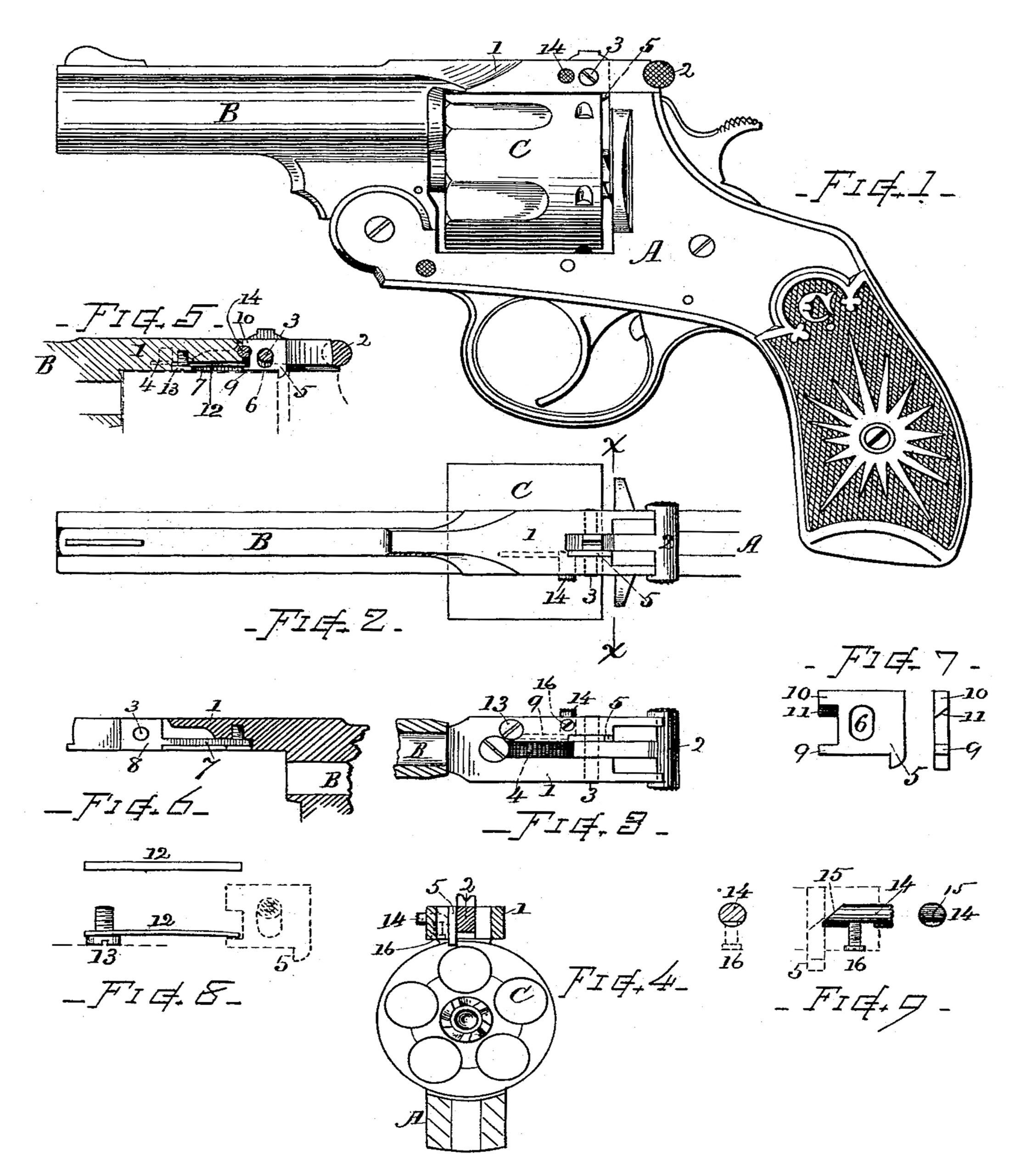
In the drawings, Figure 1 is a side view of the revolver embracing my invention. Fig. 2 is a top view of the same with the handle omitted. Fig. 3 is a bottom view of the barrel-strap and catch mechanism. Fig. 4 is a transverse section at line x x. Fig. 5 is a longitudinal section of the barrel-strap, showing the arrangement of the cylinder-catch and its spring. Fig. 6 is a longitudinal section of the barrel-strap, showing the recess for containing the cylinder-catch and its spring. Fig. 7 shows in detail the form of the cylinder-catch. Fig. 8 shows in detail the form of the cylinder-catch spring. Fig. 9 shows in detail the construction of the retracting-stud for unlocking the cylinder-catch.
Referring to parts, A denotes the frame, B the barrel, and C the cylinder, which parts may be constructed and arranged as heretofore employed in that class of revolvers wherein the barrel is hinged to the fore end of the frame and has a rearward extension or connecting-strap 1 over the top of the cylinder, and is detachably locked to the upwardly-projecting part of the frame by a suitable catch, the cylinder being supported to rotate on a quill or arbor fixed in the barrel-hinging bracket in well-known manner, and from which the cylinder can be slipped off rearwardly when desired.
In the construction of my present revolver the barrel-catch 2, which latches or locks the barrel-strap 1 to the upwardly-extended portion of the frame A, is made of well-known form, together with its transversely-disposed pivot-stud 3 and the spring 4, whereby it is held depressed, said spring being arranged and seated within the central vertical recess formed in the under side of the barrel-strap and confined by a screw, substantially in usual manner.
The cylinder-catch 5, which is the prime feature of my invention, is constructed and combined therewith as follows: In the metal. of the barrel-strap 1, adjacent to the seat of the spring 4 and opening from the central recess, I form a narrow lateral groove 7, that extends longitudinally and near the lower side of the barrel-strap, (see Fig. 6,) and at one side of the barrel-catch at the position of its pivot-bolt 3, I form a lateral enlargement of the opening by a space or recess 8, the lateral groove 7 and recess 8 being substantially of the same lateral width. The cylinder stop or catch 5 occupies position in the space 8, while its spring 12 is arranged within the groove 7. The piece which forms the cylinder-catch is shaped as indicated in Fig. 7, it being a thin plate of general rectangular form provided with a projecting end or catching lug 5 on its lower edge, fitted to lock over the rear end of the cylinder and rounded or beveled on its rear edge. Said piece has an oblong opening 6 through its center, corresponding with the width of the barrel-catch pivot-bolt 3, which passes through it when in working position. The opening 6 is longer in its upward and downward dimensions. On the front edge of the catch there is a notch or two projecting lugs 9 and 10, the upper one of which is beveled laterally, as at 11, on its lower side. Said catch-piece, when inserted within the recess 8, is retained by the pivot 3, and is free to move up and down, but not in other direction. A straight or slightly curved flat spring 12 is inserted in the lateral groove 7, its rear end resting upon or engaging the notch or lug 9 at the front edge for pressing down the cylinder-catch, while its front end is retained by a broad-headed screw 13, screwed into a threaded opening in the under side of the barrel-strap with one side of its head extending over and clamping the end of the spring 12. The spring 12 consists simply of a piece of flat steel wire cut off at proper length. (See Fig. 8.)
In the side of the barrel-strap, fitted in a suitable opening transversely to the axis of the cylinder, I arrange a reciprocating stud 14, having its inner end beveled, as at 15, for working in conjunction with a beveled lug 10 on the catch piece 5, and effecting an upward movement thereof for releasing cylinder when said stud is pressed inward with the thumb. Said stud is retained in connection with the barrel-strap by a screw 16, fitted in the under side of the strap, as indicated, the point of which screw enters a slot in the under side of the stud and confines it, so that said stud can move in and out without escaping from its recess. (See Fig. 9.)
With the arrangement herein shown, the spring 12 pressing downward on the lug 9 and the beveled lug 10 matching against the beveled end of the bolts 14, the single spring 12 serves both for depressing the cylinder-catch and for retracting the actuating-stud 14, thus giving simplicity and efficiency of action with few parts.
Other advantages of this construction are that the parts are simple and of such form that they can be manufactured cheaply and with practical facility, and also assembled without difficulty. Depression of the stud 14 releases the cylinder for ready removal from the arm, and the cylinder can be returned to place on its arbor without lifting the cylinder-catch or without raising the barrel-catch, as the rounded or inclined rear edge causes the catch to retreat when the cylinder is brought in contact therewith.
What claim as my invention, to be secured by Letters Patent, is—
1. The combination, with the barrel-strap and the cylinder in a revolver, of a vertically-sliding cylinder-catch, supported within a recess therein, and confined for upward and downward action on a bolt that passes through an oblong hole in said catch, a spring arranged within a recess in the barrel-strap, that engages for depressing said catch, and an operator or stud fitted in the side of the strap and adapted to move in opposition to the force of the spring when said stud is pressed inward and raise said catch, substantially as set forth.
2. The cylinder catch-piece constructed in rectangular form with the downwardly-extended engaging projection, and having a central oblong opening through which the hinging axis-bolt of the barrel-catch passes, said cylinder-catch being confined in the barrel-strap at the side of the barrel-catch, and means for effecting movement of said cylinder-catch for releasing and holding the cylinder, in combination with the barrel, the removable cylinder and barrel-catch, substantially as and for the purpose set forth.
3. In a revolver, in combination with the barrel-strap and cylinder, the cylinder-catch having a notch on its edge and provided with a laterally-beveled surface adjacent thereto, its operating-stud beveled on its inner end and fitted in the side of the strap to engage the catch by the adjacent beveled surfaces, and the presser-spring engaging the notch and pressing upon the catch-piece, as shown and described, whereby the throwing down of the cylinder-catch and the retraction of the operating-stud are both effected by the single flat spring, substantially as set forth.
4. In combination with the barrel-strap, having a lateral recess or groove adjacent to the barrel-catch spring-seat and the cylinder-catch, of the cylinder catch-spring, which is arranged within said lateral recess, with its end engaging a notch or lug on the cylinder-catch, and the screw 13, arranged in the under side of the barrel-strap, with its head extending over and clamping the other end of said cylinder. catch-spring, substantially as: and for the purpose set forth.
Witness my hand this 28th day of September, A. D. 1889.
HOMER M. CALDWELL.
Witnesses:
CHAS. H. BURLEIGH,
WM. A. RICHARDSON.