
US 34703
UNITED STATES PATENT OFFICE.
C. EDWARD SNEIDER, OF BALTIMORE, MARYLAND.
IMPROVEMENT IN REVOLVING FIRE-ARMS.
Specification forming part of Letters Patent No. 34,703, dated March 18, 1862.
To all whom it may concern:
Be it known that I, C.EDWARD SNEIDER, of the city of Baltimore, in the county of Baltimore and State of Maryland, have invented a new and useful Improvement in that Class of Fire-Arms known as “Revolvers;” and I do hereby declare that the following is a full, clear, and exact description of the same, reference being had to the accompanying drawings, forming part of this specification, in which–
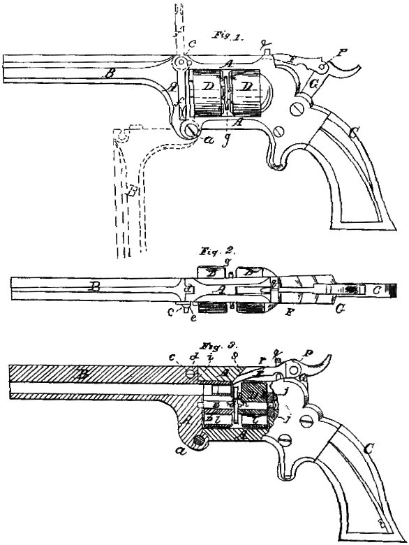
Figure l is a side view of a pistol with my improvements. Fig. 2 is a top view of the same. Fig. 3 exhibits a central longitudinal section of the same.
Similar letters of reference indicate corresponding parts in the several figures.
My invention consists in the employment, in a revolver, of two many-chambered cylinders or series of revolving chambers arranged breech to breech upon the same axis-pin, so that when all the chambers in one of them have been discharged their position can be reversed to enable the chambers in the other one to be discharged.
It also consists in a hammer of peculiar construction applied to operate in connection with such cylinders.
To enable others skilled in the art to make and use my invention, I will proceed to describe its construction and operation.
The frame A, which connects the barrel B with the stock C, and which contains the two many-chambered cylinders D D, is of substantially similar form to that of revolvers having but one cylinder, except that it is made sufficiently longer to contain the two cylinders. To provide for the removal of the cylinders and their axis pin E, the said frame is made to open at the front upper corner, in the manner illustrated by dotted outline in Fig. 1, by a movement on a hinge, a, at its front lower corner, and to secure the said frame in a closed condition with the cylinders and axis-pin in place it is fitted at its place of opening with a locking-pin, c, passing through the cheeks e e of a mortise in the upper part and through a tenon, d, in the front part of the frame. The portion of the said pin c which passes through the mortise-cheek is of round form, but the portion which passes through the tenon is half round, as shown in section in Fig. 3, and the circular hole made in the tenon for the reception of the said pin has an opening, i, of a width equal to half the diameter of the said hole cut from it to the end of the tenon, the said opening being below the center of the hole, as shown in the last-mentioned figure. The pin c is furnished at one end with a short lever, f, by which it can be turned from the position shown in Fig. 3, in which its half-round portion is above the opening i and locks the frame in a closed condition, to the position in which said portion is opposite to the opening i and the frame is unlocked, and vice versa. The lower position of the lever (shown in Fig. 1 in bold outline) corresponds with the position of the pin, (shown in Fig. 3,) and the upper position of the said lever (shown in dotted outline in Fig. 1) represents the position to which the lever is brought to unlock the frame.
The cylinders D D are bored through for the reception of the axis-pin, and have their several chambers, l l, bored right through them. Each has at its breech end a hub, b, which is concentric with its axis, and has in the opposite end a pin-hole for the reception of a pin, h, which projects from the face of the recoil pin or ratchet-pin j.
The axis-pin E consists of a straight pin having a broad collar, g, at the middle of its length, and having a small key-like protuberance, n, on each side of the said collar to enter a notch in the breech end of one of the cylinders, D D, which, being placed upon the axis-pin upon opposite sides of the collar g, with their breech ends facing each other, are connected by the said protuberances in such a manner that rotary motion imparted to one of them from the ratchet-pin j will be imparted through the axis pin to the other one. The axis-pin is long enough to protrude through both cylinders when they are close up to the collar g, and when the pin and cylinders are in place one of the protruding ends is received in a hole in the center of the ratchet-pin j and the other in a bearing in the front part of the frame. The ratchet-pin may have rotary motion imparted to it in the manner common to that employed for producing the rotary motion of the cylinders of other revolvers.
The chambers of the cylinders are loaded at their breech ends with metallic cartridges m m, the flanges of which remain outside of the chambers between the cylinders and the collar g, which serves to keep them in their places in the cylinders. The cartridges are put in the chambers before the cylinders are placed on the breech-pin. The collar g must not be large enough to completely cover the cartridges, as portions of them must be left exposed for being struck by the hammer, which is required to reach over the rearmost cylinder to strike the cartridges in the front one. As both cylinders are alike and both ends of the axis-pin alike, it does not matter, when both cylinders are loaded, which cylinder is placed in front next the barrel and which next the ratchet-pin and lock. The firing and repetition of the fire are effected in the same manner as with any other revolver, until all the charges in the front cylinder have been used, and the frame A is then opened, the two cylinders and the axis pin taken out together and put back again in a reversed position, and the frame closed again, all of which can be done very quickly, and all is then ready for using the charges of the second cylinder.
The hammer F G, which I employ in connection with this system of cylinders, has its head F made in a separate piece from the shank G and binged or pivoted thereto, as shown at p in Figs. 1 and 3. The head F so constructed and applied, works under a small bridge-piece, q, on the back part of the top of the frame A, over a fixed guide-pin, r, arranged under the said bridge, and through a slot in the top of the said frame, the front part of the said slot being beveled inward at its frontend, as shown at s in Fig. 3, and the under side of and front portion of the upper side of the said head are so formed that the hammer in passing forward and backwark will be guided by the pin r and bevel s in such manner as to clear the rear cylinder and the collar g of the axis-pin, but to strike the flanges of the cartridges contained in the forward cylinder.
It may be practicable to have the two cylinders made of one piece of metal, or, in other words, to use two series of chambers in opposite ends of a cylinder, and to make the cylinders with journals instead of with an independent axis-pin, and I consider such modification as embraced in my invention.
What I claim as my invention, and desire to secure by Letters Patent, is–
1. The employment, in a revolver, of two many-chambered cylinders or series of revolving chambers, arranged breech to breech upon the same axis-pin, substantially as and for the purpose herein described.
2. The combination of the guides q r s with a pivoted hammer-head, F, employed in connection with a revolving chambered cylinder, in the manner and for the purposes shown and explained.
C. EWARD SNEIDER.
Witnesses:
J. D. MORTIZ,
J. POULTNEY.