
US 34803
UNITED STATES PATENT OFFICE.
C. R. ALSOP, OF MIDDLETOWN, CONNECTICUT, ASSIGNOR TO J. W. ALSOP, – OF NEW YORK, N.Y.
IMPROVEMENT IN REVOLVING FIRE-ARMS.
Specification forming part of Letters Patent No. 34803, dated March 25, 1862.
To all whom it may concern:
Be it known that I, CHARLES R. ALSOP, of Middletown, in the county of Middlesex and State of Connecticut, have invented certain new and useful Improvements in that class of Fire-Arms known as “Revolvers;” and I do hereby declare that the following is a full, clear, and exact description of the same, reference being hail to the accompanying drawings, forming part of this specification, in which–
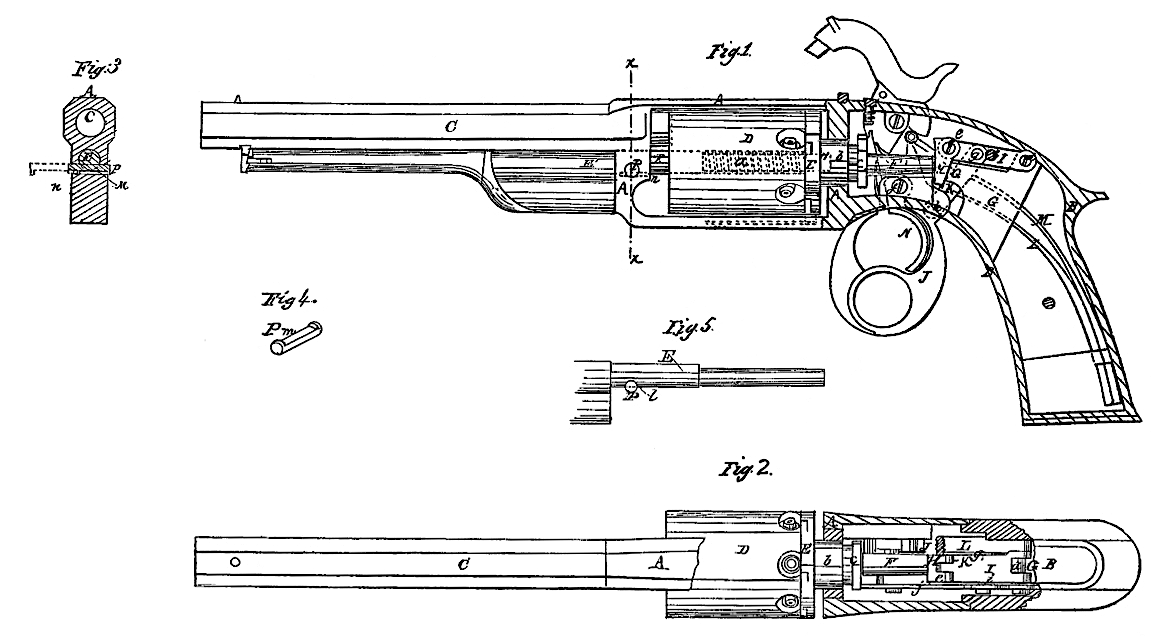
Figure 1 is a side view, partly in section, of a pistol with my improvements. Fig. 2 is a top view of the same, having the breech, stock, and frame partly broken away to show the interior mechanism. Fig. 3 is a transverse section of the same in the plane indicated by the line x x in Fig. 1. Fig. 4 is a perspective view of the pin which secures the cylinder axis-pin to the frame. Fig. 5 exhibits a side view of the cylinder axis-pin and end view of the pin shown in Fig. 4.
Similar letters of reference indicate corresponding parts in the several figures.
My invention relates to those revolvers in which a many-chambered cylinder rotating on an axis parallel with the bore of a stationary barrel is used.
It consists, first, in a novel mode of applying and operating a wedge in rear of the rotating chambered cylinder for the purpose of making tight joints between the chambers and the cylinder while firing, but of permitting the cylinder to clear the barrel in revolving.
It also consists in an improved mode of securing the cylinder axis-pin to the breech frame, which admits of its easy withdrawal to permit the removal of the cylinder.
To enable others skilled in the art to make and use my invention, I will proceed to describe its construction and operation.
A represents the cylinder-frame, made in the same piece with the stock-frame B, and having screwed into its front part the stationary barrel C.
D is the cylinder, fitted to rotate freely upon the fixed axis-pin E, which is secured in the frame B, and which enters a hole provided for it in the rotating recoil-shield E’’, against which the cylinder is always held by a spiral spring, a, (shown in dotted outline in Fig. 1,) coiled round the pin E. The rotating recoil-shield is furnished at its rear with a shaft, F, on which is a journal, b, fitted to a bearing in the back of the cylinder-frame A, and on which is also formed and secured the circular ratchet c, by which the revolution of the recoil-shield and the cylinder is effected.
G is a fixed brace or abutment, made in the same casting with or rigidly secured within the stock-frame B in rear of the shaft F of the rotating recoil-shield, for the purpose of constituting a bearing for the wedge H, by which the cylinder is forced up toward the barrel before firing. This wedge, which has its thickest part upward, is arranged to work between the said brace or abutment G and the rear end of the shaft of the recoil-shield E’’, and is attached at its head by a pin, e, to a lever, I, which works on a fixed fulcrum-pin, d, which is secured in the upper part of the said brace or abutment. The lever, I may derive the necessary movement to operate the wedge H from the hammer or from mechanism employed to cock the hammer. In the example of my invention represented in the drawings it derives motion from a finger-lever, J, which is employed to effect the cocking of the hammer and the revolution of the cylinder, the said finger-lever J working on the fulcrum-pin f, and being connected with the lever I by a link, K, and joint-pins g h. The same lever I also carries a pin, i, which serves to operate the dog j, (see Fig. 2.) which works upon the fixed pin d, and acts upon the ratchet c to effect the rotation of the cylinder.
The finger-lever J has applied to it within the frame B a strong spring, L, which is arranged below the mainspring M of the lock in such a manner that it tends to throw forward the lower part of the finger-lever, which hangs below the stock, and thus to draw down the lever I, and so to force the wedge between the abutment G and the shaft F of the recoil-shield against the cylinder and bring the cylinder tightly against the barrel. When the lower part of the finger-lever, is drawn backward by the finger to cock the hammer and cause the revolution of the recoil-shield and cylinder to bring a new chamber in line with the barrel, the link K raises the lever I, which carries the wedge upward between the abutment G and the back of the shaft F of the recoil-shield, and so allows the recoil-shield and cylinder to be forced back by the spring a and the cylinder D to clear the barrel in its revolution, which, owing to the arrangement of the dog j, does not commence till after the wedge is started. When the finger-lever J is relieved of the backward pressure of the finger and left under the uncontrolled influence of the spring L the said spring acts upon it to throw its lower part forward and to make it draw down the link K, lever I, and wedge H, and so to make the said wedge, by its action between the abutment G and shaft F, force forward the cylinder, one of whose chambers has been left opposite the barrel by the action of the dog j. The mouths of the chambers and rear muzzle of the barrel being properly constructed to fit each other, this action of the wedge makes a perfectly tight joint between the barrel and the chamber which is opposite to it, and preserves the tightness of the said joint while the fire is effected by the trigger N, for the abutment being perfectly solid and forming a bearing for the solid wedge, it is impossible that the cylinder and recoil-shield can be driven back by the force of the explosion of the charge. The wedge H may have either straight or curved faces.
The fixed cylinder axis-pin E, upon which the cylinder D rotates, and to whose head E’ the rammer is attached, passes through and fits snugly into the front part of the frame A, and is secured to the frame by a slightly tapered pin, P, which passes transversely through the said frame and through a notch, l, in the lower part of the axis-pin, as shown in Fig. 5. The hole for the said pin is, however, perfectly round all the way through, being formed by drilling through the frame and axis-pin while the latter is in the former. The pin P has a flat-bottomed recess, m, filed in its under side, extending nearly its whole length, leaving only a short piece at each end of perfectly round form, and after the said pin P is inserted a much smaller pin, n, Figs. 1 and 2, is inserted in a direction transverse to the said pin P into a hole so arranged for it in the frame A that it passes through the recess m of the said pin P, so near to one side of the frame that it (the smaller pin n) will allow the said pin P to be drawn or pushed out far enough for the frame to be perfectly clear of the axis-pin E, and to allow the latter to be drawn forward out of the cylinder and the frame A, but will prevent the said pin P being drawn out altogether from the frame.
Fig. 3 shows the pin P in bold outline in its place, locking the axis-pin, and shows it in dotted outline drawn out far enough to release the axis-pin. By this construction of and mode of applying and securing the pin P great convenience is afforded for taking out and replacing the cylinder axis-pin and cylinder, as the pin P can never be lost.
In view of the patents of H. S. North, No. 15,144, and North and Skinner, No. 8,982, I do not claim giving the cylinder a longitudinal movement toward and from the barrel, nor the use of a wedge for this purpose applied otherwise than substantially as herein specified; but
What I claim as my invention, and desire to secure by Letters Patent, is–
The arrangement of a wedge, H, with the rear of the recoil-shield shaft F and stationary abutment or bearing G, substantially as herein shown and described, for the purposes set forth.
CHAS. R. ALSOP.
Witnesses:
B. GIROUX,
M. M. LIVINGSTON.