
US 35067
UNITED STATES PATENT OFFICE.
ETHAN ALLEN, OF WORCESTER, MASSACHUSETTS.
IMPROVEMENT IN REVOLVING FIRE-ARMS.
Specification forming part of Letters Patent No. 35,067, dated April 29, 1862.
To all whom it may concern:
Beit known that I, ETHAN ALLEN, of Worcester, in the county of Worcester, in the State of Massachusetts, have invented a new and Improved Mode of Constructing Revolving Fire-Arms; and I do hereby declare that the following is a full and exact description thereof, reference being had to the accompanying drawings, and to the letters of reference marked thereon, in which—
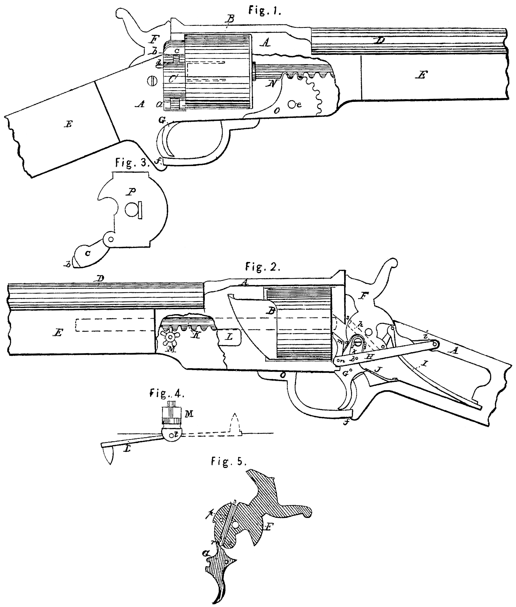
Figure 1 is an elevation of the revolving arm, being broken off at either end, and part of the frame removed in front of the cylinder to show the gears. Fig. 2 is an elevation of the same, showing the opposite side of the arm with a portion of the frame removed in the rear of the cylinder to show the construction of the lock-work, and a portion of the front end of the frame removed to show the mechanism for removing the center-pin. Fig. 3 is an end view of the recoil-plate, showing the latch, which is let down for the insertion of the cartridge. Fig. 4 is a top view of the crank and pinion for removing the center-pin, and Fig. 5 is a vertical sectional view of the cock and trigger through the center of each, showing the operation of the screw to regulate the notch.
The nature of my invention consists in providing the latch of revolving fire-arms which load with a metallic or other cartridge with a tongue or lip, which is received into a corresponding recess in the frame of the arm, which holds the latch securely and renders it perfectly safe in case of an accidental discharge of the cartridge opposite or in range of the latch or opening. I also provide the sliding pin or plunger, which is used for the purpose of removing the cartridge-shells after being exploded, with a head of sufficient size to come in contact with the edge of the shell nearest to the front end of the cylinder, and thereby save nearly one-half in the action of the sliding pin over other modes in common use, where the pin presses against the inside of the head of the cartridge-shell.
Another part of my invention consists in so constructing the lever for revolving the cylinder that the part that comes next to the cylinder is lifted nearly perpendicular to the rear face of the cylinder, thereby turning it with greater ease than by the common method, where the turning-lever is diagonal to the face I also regulate the size of the notch in the cock known as the “whole-cock” notch by extending a screw down through the cock, so that by turning the screw, which can be done without removing any of the parts, I an enabled to have the piece discharged by a very slight pull of the trigger or otherwise, at the option of the person firing.
Another part of my invention is to provide for removing the center-pin on which the cylinder revolves, which is done by providing the under side of the pin, on the end farthest from the play corresponding cogs of a pinion, and is turned by a crank that folds into the frame when not in use, orit can be turned by a wrench or screw-driver without the use of the crank. By turning the crank the pin is turned out into the stock of the arm, which relieves the cylinder, and it is easily removed.
My improvements will be more fully understood by reference to the accompanying drawings, in which—
A represents the frame of a revolving gun, B; the cylinder with the chambers extending entirely through the block; C, the latch; D, the barrel; E, the stock; F, the cock; G, the trigger; H, the li?ting-lever for revolving the cylinder, I the mainspring; J, the trigger-spring; K, the center-pin on which the cylinder revolves; M, the pinion; Li, the crank for removing the center-pin; N, the sliding pin or plunger for removing the cartridge-shells after being discharged; O, the lever for operating the sliding pin or plunger, and P the recoil-plate.
The latch C is hung to frame A at a, and is provided with a tongue, b, which is received into a corresponding groove or opening, as seen at c, Fig. 1.
d is a spring which, in connection with the projecting tongue b, holds the latch C securely when it is closed, and it can be easily opened when required for the purpose of inserting the charges.
The sliding pin N is carried through the cylinder by the lever O, which is hung at e, and being unhooked at f is carried round on dotted lines, as seen at g, which carries the sliding pin N through the cylinder, and the head h of pin N comes in contact with the edge of the cartridge, as indicated by dotted lines, and latch C being open, the cartridge shell is expelled, and the operation is repeated till all the shells have been ejected.
The lever EI is hung to frame A at i, and to cock F at j, and the part k is jointed to the long lever H at l, and the part in is jointed to long lever H at n, and is pressed against the cylinder by spring o. As the cock is raised the part in comes in contact with the notches in the cylinder B, and turns it each time the required distance to bring each successive chamber in line with the barrel. It will be noticed that the action of the lever can be graduated by hanging the part k farther from or nearer to the center of the lock. There is a screw, p, Fig. 5, which extends through the cock, the lower end of which comes in contact with trigger G, and graduates the size of the notch, as seen at r, Fig. 5. This screw p can be turned at any time from the top side of the cock, as seen at S, Figs, 2 and 5, the convenience of which will be readily seen, as it requires no part of the arm to be removed.
The center-pin K, Fig. 2, on which the cylinder revolves, is furnished with a succession of cogs, as seen in the drawings, into which play corresponding cogs of a pinion, M, which is hung in the front end of the frame and has a crank, L, jointed to it at t, Fig. 4, and when it is not in use it is folded into the frame, as indicated by dotted lines in Fig. 4. When it is found necessary to remove the cylinder for cleaning or other purposes the crank L is folded out of the frame, and by revolving the pinion M by means of the crank L the pin K is carried back into the stock, as indicated by dotted lines, Fig. 2, and the cylinder is released. The cylinder being replaced, the crank is turned in the opposite direction and the pin is carried back through the cylinder, and the crank L being again folded into the frame, the pin K is held securely in place.
Parts not mentioned being the same as those in common use in this class of arms, a further description is not deemed necessary.
What I claim as my invention, and desire to secure by Letters Patent, is—
1. The combination of parts m, k, and H of lever, H being hung at the cock, substantially as specified, and for the purpose set forth.
2. Inserting screw p in cock F in such a manner that the size of the notch can be regulated from the outside of the arm by turning said screw, as described.
3. The rack k and pinion M for operating the center-pin, substantially as specified.
ETHAN ALLEN.
Witnesses:
Henry C. Wadsworth,
George W. Fairfield.