
British 2662
LETTERS PATENT to John Piddington, of 53, Gracechurch Street, in the City of London, Patent Agent, for the Invention of “ Impbove-ments in Revolvees and in REVOLVING Fibe-abms.”—A communication from abroad by 0. P. Tackels, Captain of Infantry, residing at Huy, in the Kingdom of Belgium.
Sealed the 4th March 1873, and dated the 7th September 1872.
PROVISIONAL SPECIFICATION left by the said John Piddington at the Office of the Commissioners of Patents, with his Petition, on the 7th September 1872.
I, John Piddington, of 53, Gracechurch Street, in the City of London, Patent Agent, do hereby declare the nature of the said Invention for “ Improvements in Revolvers and in Revolving Fire-arms,” being a communication to me from abroad by C. E. Tackels, Captain of Infantry, residing at Huy, in the Kingdom of Belgium, to be as follows:—
The improvements embraced by this Invention are more especially applicable to revolving pistols or revolving fire-arms in which central-fire cartridges are used, the extraction of the expended cartridge cases being produced by automatic mechanism which is put in motion hy the action of opening the pistol or fire-arm. The pistol or fire-arm is jointed and arranged so as to turn on a pivot or hinge at the lower part of the front end of the frame or body, and is locked or held firmly in position for discharge, or when not required to he intentionally opened, by a self-acting spring latch or pedal.
The pistol or fire-arm is divided into two parts united by and turning upon a hinge constructed at the front end of the foot or lower portion of the frame or body of the pistol or fire-arm, and the spring latch or lock which secures and unites the two parts firmly in contact is attached to the opposite end of the frame or body. This spring latch or pedal is disengaged by pressure, and thus permits of the free rotary movement of the barrel with the cylinder and parts connected therewith upon the hinge, which is provided with a projection so arranged as to put in motion a tube carrying at its rear end an extractor of a star form, and which works through the cylinder and turns therewith upon its axis, but having also a to-and-fro movement in connection with a pin or pivot upon which it is mounted, and which pin or pivot serves as the axis upon which the cylinder revolves, and by means of which the cylinder with its adjuncts is attached to the frame or body of the pistol or firearm. The movement for the extraction and rejection of the expended cartridge cases is produced by and dependent upon the lever or projection formed upon the hinge, which in the act of opening the pistol or firearm is brought in contact with the end of the pin or pivot, and the return motion of the pin with the extractor is produced by a spiral spring which surrounds the pin or pivot.
In order to obviate the disadvantages attendant upon the escape of gas from faulty cartridges, and the inconvenience resulting from the fouling thus occasioned, which more or less impedes the proper working of the pistol or fire-arm, and obstructs the regular action of the lifter and ratchet arrangement of or upon the cylinder as ordinarily employed, the recoil face of the frame or body of the pistol or fire-arm against which the rear or chamber end of the cylinder is in contact when the pistol or fire-arm is closed is made perfectly solid, except the opening to permit the passage of the nose of the hammer. The trigger spring ordinarily placed in a trough formed in the lower part or foot of the frame or body is dispensed with, and the foot is formed solid. By these means the entry of gas or powder-fouling into the lock or into the working mechanism of the pistol or fire-arm is completely prevented. The rotation of the cylinder is produced by an oscillating rod attached to and receiving its motion from the trigger by means of a guide, the movement thus produced being communicated to the cylinder, which has teeth or ratchets formed upon its outer rearward circumference, in which one extremity of the oscillating rod engages, and by the movement of the trigger for the purpose of cocking or discharging the pistol or fire-arm, or by the independent movement of the hammer prior to discharge, the rotation of the cylinder is effected. By means of a plate placed on the under side of the foot or body of the pistol or fire-arm, and so arranged as to be free to slide between two shoulders, the action of opening the pistol or fire-arm by turning the forward end upon its hinge joint brings a portion of the joiht arranged for that purpose in contact with the sliding plate, and by its rearward movement the hammer is brought to the position of half-cock.
As a consequence of these modifications and the omission of the lifter, ratchet, and accessories ordinarily employed, a more simple, solid, and efficient arrangement and disposition of the hammer and mainspring as also of the trigger is obtained, and for the greater facility of examination of the interior of the mechanism a moveable side plate is arranged, which by the withdrawal of a single screw can readily be removed, and the working parts of the mechanism of the pistol or fire-arm thereby exposed to view for cleaning, oiling, or other purposes.
SPECIFICATION in pursuance of the conditions of the Letters Patent, filed by the said John Piddington in the Great Seal Patent Office on the 7th March 1873.
TO ALL TO WHOM THESE PRESENTS SHALL COME, I, John Piddington, of 53, Gracechurch Street, in the City of London, Patent Agent, send greeting.
WHEREAS Her most Excellent Majesty Queen Victoria, by Her Letters Patent, bearing date the Seventh day of September, in the year of our Lord One thousand eight hundred and seventy-two, in the thirty-sixth year of Her reign, did, for Herself, Her heirs and successors, give and grant unto me, the said John Piddington, Her special licence that I, the said John Piddington, my executors, administrators, and assigns, or such others as I, the said John Piddington, my executors, administrators, and assigns, should at any time agree with, and no others, from time to time and at all times thereafter during the term therein expressed, should and lawfully might make, use, exercise, and vend, within the United Kingdom of Great Britain and Ireland, the Channel Islands, and Isle of Man, an Invention for “ Improvements in Revolvers and in Revolving FIBE-ABMs,,, being a communication to me from abroad by C. F. Tackels, Captain of Infantry, residing at Huy, in the Kingdom of Belgium, upon the condition (amongst others) that I, the said John Piddington, my executors or administrators, by an instrument in writing under my, or their, or one of their hands and seals, should particularly describe and ascertain the nature of the said Invention, and in what manner the same was to be performed, and cause the same to be filed in the Great Seal Patent Office within six calendar months next and immediately after the date of the said Letters Patent.
NOW KNOW YE, that I, the said John Piddington, do hereby declare the nature of the said Invention, and in what manner the same is to be performed, to be particularly described and ascertained in and by the following statement, reference being had to the annexed Drawings, and to the figures and letters marked thereon, that is to say:—
The improvements embraced by this Invention are more especially applicable to revolving pistols or revolving fire-arms in which central-fire cartridges are employed, and relate more especially to that class of revolvers in which the extraction of the expended cartridge cases is effected by automatic mechanism receiving its motion from the action of turning the barrel of the revolver with its cylinder or charge chamber upon a hinged joint, but the essential elements of this Invention are equally applicable to revolving pistols in which the barrel is fixed to the body, and the extraction of the expended cartridge cases is effected by a rod or other means; in this latter case, however, the body or frame of the pistol would require to be adapted to the altered requirements.
In applying these improvements to a revolving pistol having the barrel jointed to the lower forward end of the frame or body, the pistol is composed of two parts, united by and turning upon the axis of this joint, the one part comprising the barrel with its foot or support to which the axis of the cylinder or revolving chamber with its adjuncts is attached, and which support forms with the forward end of the foot of the frame or body the hinge above described. The barrel has at its rear end a strap or bar arranged to close or shut into the upper portion of the recoil surface of the frame or body, where it is maintained solidly by a spring latch or catch, which secures and unites the barrel and its adjuncts to the frame or body of the pistol for discharge, or when not required to be intentionally opened this frame or body comprising the butt and the mechanism for discharging the cartridges producing the rotation of the cylinder and maintaining the chambers of the cylinder in perfect conformity with the barrel during the explosion of the cartridges.
The pistol is opened by exerting a slight pressure upon the thumb piece of the spring latch, which is thus turned upon its pin or pivot, and whereby the hammer is first moved backwards to the safety bent, the catch of the latch becomes disengaged from the screw, the head of which serves to maintain it in position, and the strap or bar of the barrel is disengaged, leaving the barrel with its adjuncts free to turn upon the pivot of its hinge. In doing so the lever or projection solid to the front end of the frame or body engages the axis upon which the extractor is mounted, and thereby produces the extraction of the expended cartridge cases, the extractor which is of a starlike form remaining projecting beyond the rear face of the cylinder until the arm is re-charged, when it is returned into position by the reverse action of the fixed lever, or I sometimes employ a spiral spring which surrounds the axis of the extractor, and by which the extractor is returned into position level or nearly so with the rear face of the cylinder, and this return motion may or may not be completed by the reverse action of the fixed lever, the action of the spiral spring bringing the barrel and adjuncts to an angle of forty-five degrees or thereabout with the frame or body of the pistol after the extraction of the expended cartridge cases has been completely effected. The cylinder with its adjuncts is securely attached to the support forming part with the barrel by a key or screw pin, which however can be removed at discretion when it is desired to dismount this portion of the mechanism* The rotation of the cylinder is effected by forming the ratchet upon the outer circumference of the cylinder or charge chamber*
The mode of producing the rotation of the cylinder and retaining its chambers successively in position relatively to the axis of the barrel during the discharge of the cartridge forms one of the improvements to which this Patent has reference. I dispense with the lifter and ratchet arrangements ordinarily employed to produce the rotation of the cylinder or charge chamber, which enables me to make the recoil surface of the body of the pistol solid, except the opening, which permits of the passage of the nose of the hammer to ignite the cartridge and thereby the escape of gas or of powder fouling resulting from faulty cartridges is prevented from entering the mechanism and obstructing the regular action of the ratchet and lifter and impeding more or less the proper working of the pistol,
In these my improvements I produce the rotation of the cylinder or charge chamber by an oscillating lever or plate moving upon a pivot fixed to the recoil surface of the frame or body of the pistol. This oscillating lever or plate has an arm or spur which projects slightly beyond the outer circumference of the recoil surface, and engages with the teeth of the ratchet upon the cylinder, when the barrel and adjuncts are closed and locked in position. This oscillating plate is also arranged in such a manner that a guide receiving its motion from the trigger causes the rod or plate to oscillate, and by means of the arm or spur which is maintained in continual contact with the rear end of the cylinder, when the pistol is closed by means of a spiral or other spring engages alternately the teeth of the ratchet and lifts or rotates the cylinder the proportion or distance necessary to bring each chamber successively in line with the barrel, where it is firmly maintained during the discharge of the cartridges by a regulator, which obedient to the action and movement of the trigger enters successively notches formed upon the periphery of the cylinder or is alternately retired therefrom.
These modifications in the mode of rotating the cylinder necessitate a special adaptation of the trigger, which is formed with an arm or elongation arranged to receive one end of the guide which communicates motion to the oscillating plate, this elongation serving also to produce the movement of the regulator simultaneously with that of the oscillating plp-te. In addition to this I form on one side of the trigger a sinking to receive a piece, which turning upon the same axis as the trigger serves as a safety bent or stop due to a double movement, one movement dependent upon the movement of and with the trigger, the other independent of the trigger but due to the movement produced by the spring latch upon the hammer, or by moving the hammer directly by the action of the thumb on its crest. In addition to this the trigger is furnished with a spur which by the intermediary of the lifter raises the hammer to half or full cock. In this latter position the spur acts as the sear nose, which on becoming disengaged from the full bent of the hammer permits the forward movement of the hammer which produces the discharge. I dispense with the trigger spring ordinarily placed in a trough formed in the lower part or foot of the frame or body which is now formed solid, and I use a spring split for a portion of its length so as to form two blades, one acting upon the trigger, the other acting upon the safety bent or stop. At its lower end this spring unites and has two projections formed upon it for retaining and securing it in position.
The omission of the lifter ratchet and accessories ordinarily employed and the substitution of the mechanism herein described permits the employment of a more simple, solid, and efficient arrangement and disposition of the hammer and mainspring, and a greater facility of examination of the working parts of the mechanism, and their removal if necessary for cleaning, oiling, or other purposes than is ordinarily the case.
The handle or butt of the pistol is formed in a piece with the frame or body, and has a web continuous or in two or more parts as may be necessary which supports the discharging and rotating mechanism. In the upper end of this web I form or fix two pivots, the one serving as the axis of the hammer, the other of the trigger and safety bent or stop, and at or near the centre of the butt or handle I attach a key so arranged as to be free to rotate when desired, and by which the mainspring and trigger spring are compressed and secured firmly in position or are unbent for removal in case of necessity. The hammer is furnished with a swivel which engages in the ordinary manner with the fork of the mainspring; it has a lifter which is actuated by a spur formed upon the trigger, and has a half bent which engages with the independent safety bent or stop of the trigger, as also a full bent for discharge. In addition to the arrangements already described I employ a moveable side plate which is arranged to cover the working parts of the mechanism. This moveable side plate is arranged to receive and sustain the projecting ends of the fixed pivots upon which the hammer and trigger turn, and is arranged to maintain in connection with a lip or spur formed upon the frame of the butt or handle the wood of the stock on the side to which the moveable plate is adapted, this side of the wood of the stock haying a groove formed in its thickness which retains the key of the springs in its required position. The wood of the stock on the opposite side being retained by a screw from or to the web of the body and a spur upon the frame or otherwise.
The trigger guard may be formed in a piece with the frame or body, or it may be an independent piece, in which latter case I form a screw upon its forward end, by which I attach it to the under side of the fore end of the frame or body, and by means of a dovetail formed upon its rear end I arrange it to enter a slot formed for its reception in the frame, in which position it is maintained by the moveable side plate.
By the employment of the means of construction herein described the dismounting of the revolver is rendered exceedingly easy, as the whole of the mechanism can be removed with the utmost facility by withdrawing a single screw, while the replacement of the component parts is equally simple.
The process of dismounting the mechanism of a pistol of my Invention is as follows:—Remove the screw which secures the side plate to the frame or body; remove the side plate which exposes to view the entire arrangements (except the fixing of the springs) of the trigger rotating and discharging mechanism. If it is desired to remove the hammer or trigger it will be necessary to take off the side of the wooden stock, which permits the key of the springs being turned upon its axis, the springs are thereby unbent, and the one opposed to the side to which the key is turned can be removed by the fingers without the aid of any instrument whatever. The key is then turned in the opposite direction, when the second spring can be removed with equal facility. The hammer and trigger can then be lifted off their pivots, and the mechanism of rotation can also be removed if desired.
To dismount the cylinder it is necessary to free and turn the barrel upon its axis, unscrew the key which fixes the axis of the cylinder, this permits of the moveable pin or tube which carries the star extractor being withdrawn, and by unscrewing the set screw at the end of this pin the extractor can be removed from the rod, or the rod itself with its spiral spring from its tube by unscrewing the small guide.
The mechanism is replaced in the reverse order to that in which it is dismounted.
In place of moving the hammer by means of the spring latch already described, I sometimes prefer to employ a moveable plate arranged to slide on the under side of the fore end of the frame or body; this plate receives its motion from a projection formed upon the joint of the barrel or support and acts upon the trigger, thereby lifting the hammer to the half or safety bent.
I will now refer to the annexed Drawings, from which the nature of the said Invention will be more clearly understood. Similar letters of reference refer to similar parts in all the Figures.
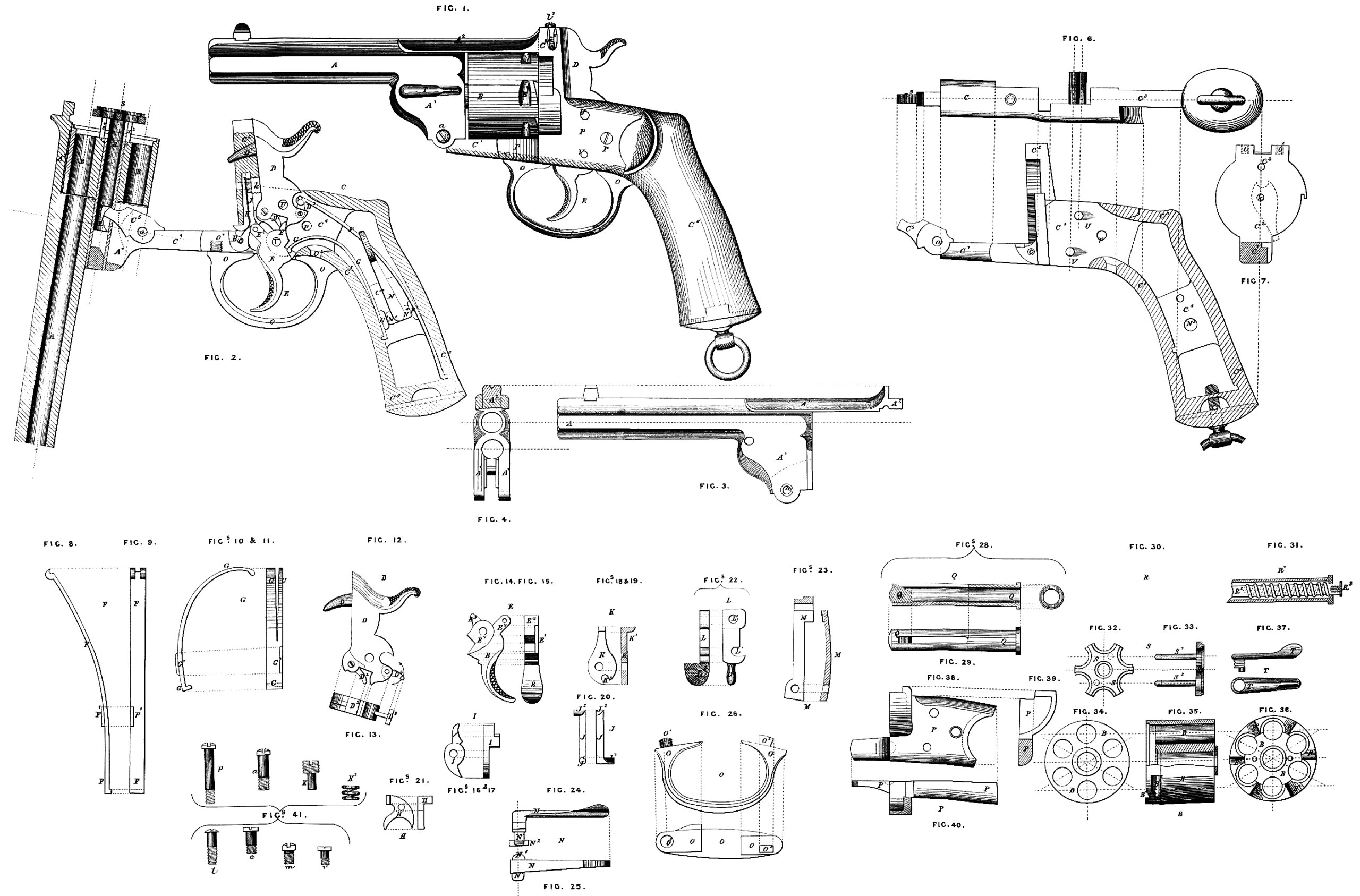
A is the barrel with its support A1 and bar A2; a is the pin or pivot upon which the barrel and its accessories turn; B is the cylinder or revolving chamber; B1,the ratchet; B2, the stop or notches with which the regulator H engages; C is the frame or body of the pistol; C1, the foot or front end; C2, the recoil face; C8, the handle or butt; C4, the webs of the butt on which the mechanism of the lock mounted; C6, the lever or projection solid to the front end of the frame, and which engages with the moveable pin It to produce the extraction of the expended cartridge cases; C6, the stock; D is the hammer; Dl, the nose; D2, the lifter; D3, the swivel; E is the trigger with a sinking E1 for the reception of the piece I, forming safety bent or stop, and with an arm or elongation E2 receiving the pinion or arm of the guide J, by means of which motion is communicated to the oscillating plate K. E8 is the spur or sear nose of the trigger; E is the mainspring; E1, the projection against which an arm or spur of the key or cramp N comes in contact; G is the trigger spring split and arranged to act independently upon the piece I forming the stop or safety bent; G1, the projection against which one arm or spur of the key N comes in contact for the compression; H is the regulator, ensuring conformity between the chambers of the cylinder and the barrel during explosion, c is a screw serving as the axis of the regulator, or a fixed axis may be employed as for the hammer and trigger. I is the stop or safety bent of the trigger; J, the guide communicating motion from the trigger to the oscillating plate K by means of J1, the arm or pinion, and J2 an oblique arm which engages with the rounded hollow K2 of the oscillating plate; K, the oscillating lever plate; K1, the arm or spur which imprints the movement of rotation upon the cylinder by means of the ratchet B1 formed upon the outward circumference of the rear end of the cylinder. K2 is a rounded hollow in which the oblique arm J2 of the guide engages; k, pivot of the oscillating lever plate K with enlarged screw head; upon this pivot is placed the spiral spring k\ which maintains the arm or spur K1 constantly in contact with the teeth of the ratchet on the rear face of the cylinder when the pistol is closed; L is the spring latch or pedal lever; l, the screw forming pivot upon which this spring latch turns, and by which it is attached to the recoil face C2 of the frame or body; l1, a screw attached also to the recoil face C2, and forming a stop to the spring latch; l2, the thumbpiece ; M, the spring to this latch; m, the screw pin or pivot by which it is attached to the frame or body of the pistol; N, the key or cramp lever, by which the main and trigger springs are secured in place or released or unbent for dismounting; Nl, the pivot; N2, the nut securing the key to the web of the frame or body; N8, hole in the web for this pivot; N4, arms acting upon the projections F1 and G1 of the springs; O is the trigger guard formed separately from the frame or body; O1, the screw; O2, the dovetail; P, the moveable side plate covering the mechanism of the lock; p, the screw pin attaching this moveable side plate to the frame or body. Q is the axis of the cylinder containing the moveable pin E, or the tube E1 with its pin E2 surrounded by a spiral spring, to the end of which pin the star extractor S is attached by the screw E8; Ql is the shoulder of the axis, which serves to maintain the cylinder in position; r is the set screw guiding the extractor pin E in the tube Q; S, extractor in form of a star with guides s1 and s2; T, key by which the axis Q carrying the cylinder and adjuncts is attached to the support A1 of the barrel. U, fixed pivot serving as the axis of the hammer D; V, fixed pivot serving as the axis of the trigger E, and safety bent or stop I.
The annexed Drawings represent on a scale of actual grandeur a pistol constructed in conformity with the foregoing descriptions, the chief component parts being also shewn in detail.
Figure 1 is a side elevation, the whole of the parts being in repose and the arm closed.
Figure 2 is a longitudinal sectional elevation, the moveable side plate and the wood of the stock being removed to expose the mechanism of the lock and means employed for rotating and retaining the cylinder chambers successively in conformity with the axis of the barrel, and also the method of straining and fixing the trigger and mainsprings. The barrel is drawn, turned upon its axis, and the extractor projected beyond the rear face of the cylinder. The hammer is here shown in the position it would occupy after the explosion of the cartridge had been effected and the trigger returned to its normal position. This is an error, because the hammer is always thrown hack to the safety bent before the pistol is opened and would never occupy the position here shown during the time the arm is open unless intentionally placed in this position. It would however be necessary to replace the hammer at half cock, or in the safety bent before the arm could be closed, otherwise it would he impossible for the end of the strap or bar of the barrel to close into the upper portion of the recoil surface of the frame or body, this movement of the hammer being assured by the spring catch.
Figure 3 a side elevation, and Figure 4 a rear end view of the barrel with its support and bar.
Figure 5 a sectional side view, Figure 6 an under side view, and Figure 7 a front view of the recoil surface of the body or frame of the pistol. The position of the oscillating lever plate is shewn by dotted lines upon the recoil surface of the frame or body.
Figure 8 a side view, and Figure 9 a front view of the main spring.
Figure 10 a side view, and Figure 11 a front view of the combined trigger and stop or safety bent spring.
Figure 12 a side view, and Figure 13 an under side view of the hammer.
Figure 14 a side view, and Figure 15 a back view of the trigger.
Figure 16 a side view, and Figure 17 a back view of the stop or safety bent of the trigger.
Figure 18 is a side view, and Figure 19 a sectional view of the oscillating plate.
Figures 20 front and side views of the guide which communicates motion to the oscillating plate from the trigger.
Figures 21 side and end views of the regulator.
Figures 22 side and under side views of the spring latch or catch.
Figures 23 side and sectional views of the spring which actuates the spring latch.
Figure 24 side view, and Figure 25 top view of the key or cramped lever which fixes and retains the main and trigger springs in position.
Figure 26 side view, and Figure 27 a top view of an independent trigger guard.
Figures 28 sectional views, and Figure 29 a top view of the axis of the cylinder.
Figure 30 side view of the moveable pin which carries the star extractor.
Figure 31 sectional view of a modified arrangement of the moveable pin to carry the star extractor; in this instance a spiral spring is employed by which the extractor is returned flush with the face of the cylinder.
Figure 32 is a front end view of the star extractor.
Figure 33 is a side view of the extractor and guides.
Figure 34 is a front end view of the cylinder.
Figure 35 is a side view of the cylinder partly in section.
Figure 36 is a rear end view of the cylinder (without the extractor) showing the ratchets.
Figures 37 are side and top views of the key by which the cylinder and adjuncts are attached to the supports of the barrel.
Figure 38 is a side view, Figure 39 a front end view, and Figure 40 a top view of the moveable side plate.
Figures 41 shew a group of screws and spiral spring.
And having now described the nature of my said Invention and the manner in which the same is to be carried into effect, I declare that I do not limit myself to the precise details herein-before described and illustrated in the accompanying Drawings, as the same may be varied without departing from the essential features of my Invention, but at the same time I do not claim the whole of the parts when taken separately, but only when combined as herein-before described and illustrated in the accompanying Drawings ; but I claim as my improvements in revolvers or revolving fire-arms,—
First. The rotary movement of the cylinder by means of an oscillating rod, lever or plate receiving its motion from the trigger by means of a guide or intermediary lever, and being sustained in proximity with the teeth of the ratchet formed on the rear face of the cylinder when the latter is closed into position by means of a spiral or other spring and the retention of the chambers of the cylinder in conformity with the axis of the barrel during discharge by means of the regulator obedient to the action of the trigger, substantially as herein described and illustrated in the accompanying Drawings.
Second. Forming the safety bent of the arm in the manner described and indicated, turning upon the same axis as the trigger and partaking of the motion imparted to the trigger, or having an independent motion, as and for the purposes named, together with the employ of a spring partially split and forming two blades, one blade acting directly upon the trigger, the other upon the safety bent or stop.
Third. The means herein described and illustrated of fixing and bending or unfixing and unbending the main and trigger springs for removal or otherwise.
Fourth. The modified arrangements herein described and illustrated of the discharging and rotating mechanism of the pistol, thereby avoiding the entry of gas or powder fouling and the consequent derangement of the internal mechanism of the pistol.
In witness whereof, I, the said John Piddington, have hereunto set my hand and seal, this Seventh day of March, in the year of our Lord One thousand eight hundred and seventy-three.
JOHN PIDDINGTON. (l.s.)