
British 2777
LETTERS PATENT to William Robert Lake, of the’ Firm of Haseltine, Lake & Co., Patent Agents, Southampton Buildings, London, for the Invention of “ Improvements in Revolving Cylinder Pistols.” A communication from abroad by Owen Jones, of Philadelphia, Pennsylvania, United States of America.
Sealed the 1st September 1876, and dated the 7th J*uly 1876.
COMPLETE SPECIFICATION filed by the said William Robert Lake at the Office of the Commissioners of Patents on the 7th July 1876.
William Robert Lake, of the Firm of Haseltine, Lake & Co., Patent Agents, Southampton Buildings, London. ” Improvements in Revolving Cylinder Pistols.” A communication from abroad by Owen Jones, of Philadelphia, Pennsylvania, United States of America.
This Invention comprises—
First. The combination with an extractor [plate for holding the cartridges of a centre pin fixed to the frame, a cylinder adapted to slide upon the centre pin, and a hinged lever barrel adapted to move the cylinder upon the pin to and from the relatively ‘fixed extractor plate.
Second. • The combination of a tilting barrel and a cylinder upon a centre pin, with an intermediate connecting device uniting the two parts, so that the movement of the former is communicated to the latter without lost motion.
Description of the Drawing.
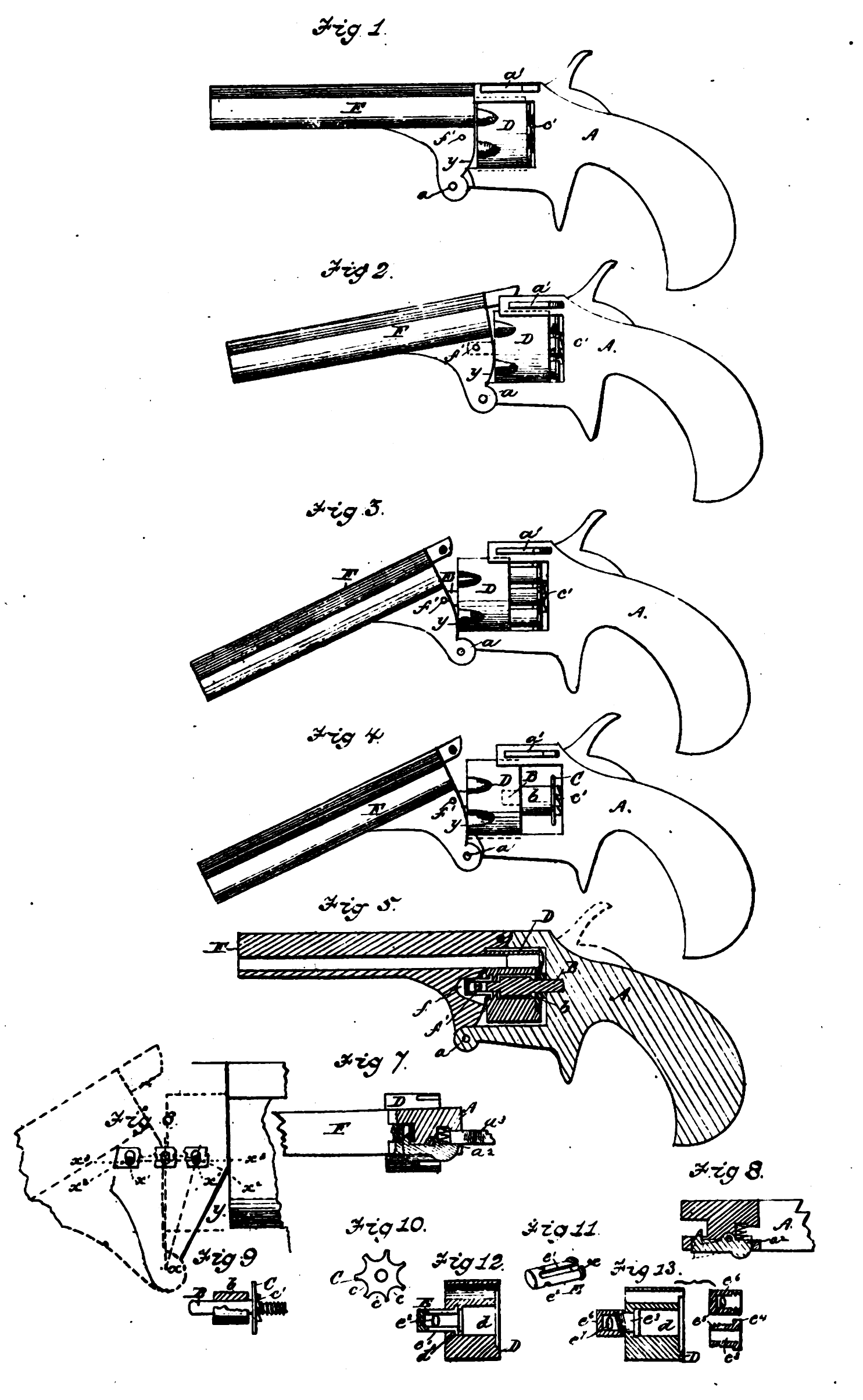
A represents the frame or stock of the pistol constructed generally in any proper manner, but provided essentially with a pivot shaft or rod a, by means of which the barrel is hinged thereto, and a catch a\ of any suitable construction, by means of which the barrel is properly locked when in its normal position.
B, Figures 4, 5, and 9, represents the centre pin of suitable length and size, which is rigidly secured at one end to the frame, and projects therefrom into the proper position to receive the cylinder, as shown in Figures 4 and 5 ; b represents a sleeve or collar which either forms a solid portion of the centre pin, as shown in Figure 5, or if independent, as shown in Figure 9, is rigidly attached thereto, as far as longitudinal movement is concerned. This is preferably extended in length to furnish a proper bearing surface for the cylinder in its longitudinal movement.
C, Figures 4, 9, and 10 represents the cartridge extractor, consisting of a disc of proper size located upon the centre pin at the rear of the collar b, which is provided with a peripheral series of recesses c. Figure 10 adapted to receive and hold the cartridges in the usual well known manner, and also with a rearward projecting series of ratchet teeth c\ adapted to be acted upon by the usual mechanism for revolving the cylinder.
D, Figures 4, 5, 12, and 13 represents the cylinder constructed generally in the usual well known manner, but provided with a central recess d, adapted to receive the centre pin and its collar, and an annular groove d1 adapted to hold the flange of the sleeve link as shown.
E, Figures 5,11, and 12 represents the sleeve link, consisting of a cylinder, made preferably of spring steel, and which is provided with flanges e at one end, and has also longitudinal slots e1 upon its sides, and the transverse slots c2, as shown. This sleeve link is attached to the cylinder by compressing its slotted end, and inserting it into the central opening until the flanges e are in line with the corresponding groove d1, into winch latter they are sprung, and held by the reaction of the metal when the same is released from compression.
If desired, however, a different form of attachment may be employed in place of the sleeve link. In Figure 13, e8 represents a stud or bolt, either hollow or solid, as may be preferred, which is provided with a head e* and threaded end e5, as shown. This is placed in position by inserting it into the opening of the cylinder from its rear end and moving it forward until its head rests against the shoulder of the cylinder, as # shown; eQ represents a threaded socket adapted to fit the threaded end of the bolt e8 and hold it against longitudinal displacement, and which is provided with an elongated opening c7, corresponding in its purpose with the elongated slots e2 of the sleeve link. By this construction, or that of the sleeve link E, the cylinder is provided with an intermediate connecting device adapted to unite it to the barrel without interfering with its freedom of revolution. F represents the barrel hinged to the frame as shown, and provided with a central recess /, Figure 5, adapted to receive the projecting end of the sleeve link E or socket e6 and a transverse pin f\ which passes through the transverse slots of the link and thus unites the cylinder and barrel. The hinge of the barrel it will be observed is located upon a line equidistant between its limit of movement in either direction, so that when the barrel is tilted the point to which the sleeve link i3 attached moves in equal arcs upon each side of the central line, and hence varies less from the horizontal plane in which the barrel moves than would be possible if the pivot was located at any other point. The relative movements of the barrel and cylinder will be better understood by referring to Figure 6, in which x represents the hinge point of the barrel x\ the pin uniting the link or sleeve of the cylinder to the barrel; the curved line x2, a2, represents the line of the pins* movement, and the straight line x8, x3, the line of movement of the slot in which the pin plays. It will be observed that the pin in its longitudinal movement varies but slightly from the horizontal line in which the link or sleeve moves, the necessary variation being permitted by the elongated form of slot as shown.
The entire length of this movement of the pin properly corresponds with the length of the cartridge to be extracted, the distance upon each side of the central line equalling one half of the cartridge’s length.
It will be observed also that the hinge point is located on the lower side of the barrel and frame, and that the lower side of the barrel is cut away at y, Figures 1 and 6, so that proper space is left for the movement of the cylinder when the barrel is tilted. The necessity of this construction will be understood when it is considered that the point of union, Figure 6, between the barrel and cylinder is farther removed from the pivot point than the parts below it, and hence as this point moving in the arc of a larger circle passes over more distance in a given time, and as the cylinder closely united to it moves with it, it follows necessarily that unless the lower portions be cut away the more rapidly moving cylinder will come in contact with them and prevent the proper movement from taking place.
By hinging the barrel at the lower side, and cutting away the said barrel, as described, it is possible to unite the barrel and cylinder closely, so that the movement of one is communicated to the other without lost motion.
a1 represents the spring catch for locking the barrel when in its normal position. This is constructed generally in any proper manner, but has essentially its rear portion a2, Figures 7 and 8, so formed as to project past the hammer head a.8, when the latter is in position to explode the cartridge, as shown in Figure 7, so that movement to unlock the barrel is impossible until the hammer head which lies in its path of movement has been removed, as shown in Figure 8. The extractor may be held from longitudinal movement on the centre pin if desired, but may also be permitted to slide with the cylinder some distance in order that an impetus may be given to the cylinder and barrel before the extractor acts (in consequence of striking the collar b) to hold the cartridge shells, this impetus being desirable in order that jammed or tightly held shells may be readily removed.
When this construction is employed the hinge point is moved forward a proper distance so that the barrel may tilt, as above described, upon a pivot equidistant from its limits of movement.
The operation of this Invention is as follows:—The general action of the pistol is of course similar to that of others of its class. The extracting mechanism acts as follows:—The cartridges having been inserted in the cylinder in the usual manner, and the pistol having been fired, the entire series of shells may be extracted at a single operation by simply unlocking the barrel and tilting it on its hinge. By this action the cylinder, which is united to the barrel by the sleeve link or sleeve is moved forward upon the centre pin, but the cartridges being held from forward movement by the relatively fixed extractor plate are consequently left unsupported and fall to the ground. The cartridge extractor is loose upon the centre pin, but connection is made between it and the cylinder by means of the cartridges, so that the cylinder is properly revolved by the usual mechanism employed for that purpose.
Some of the advantages of the above described Invention are as follows :—
The construction of the parts is exceedingly simple, and yet the mechanism is very effective in its action. The barrel is employed as a lever to extract the cartridges, and hence their removal is effected without difficulty. By locating the hinge upon the lower side of the frame and barrel, and by cutting away the latter, it is possible to closely unite the two and communicate the movement of the barrel to the cylinder without lost motion.
By locating the hinge of the barrel upon a central line between the limits of its movement the cylinder may be attached to it by an intermediate connection, having but little play or divergence from a horizontal line.
The construction of the sleeve link or hollow stud is advantageous, because it is adapted to receive the end of the centre pin, and thus hold the barrel and cylinder accurately in line with each other.
Having thus fully described the said Invention as communicated to me by my foreign correspondent, and the manner of peiforming the same, I wish it understood that I do not limit myself to the sleeve link for uniting the barrel to the cylinder, as other means of making this connection will readily suggest themselves to skilled mechanics, nor do I claim broadly the employment of a tilting barrel for actuating mechanism for extracting the cartridges ; but I claim—
First. The combination with an extractor plate for holding the cartridges of a centre pin fixed to the frame or cylinder adapted to slide upon the centre pin, and a hinged lever barrel adapted to move the cylinder upon the pin to and from the relatively fixed extractor plate as above described.
Second. The combination of a tilting barrel and a cylinder sliding upon a centre pin with an intermediate connecting device, so uniting the two parts that the movement of the former is communicated to the latter without lost motion, as above described.
Third, The combination of a fixed centre pin, a relatively fixed extractor plate, and a sliding cylinder with a tilting barrel, and mechanism for connecting the barrel to the cjdinder, the* construction being such that the cylinder is adapted to slide upon the centre pin, but is held from removal therefrom, as above described.
Fourth. In combination with a cylinder sliding on a centre pin a lever barrel hinged on its lower side, and cut away so that the cylinder and barrel are closely united and moved together without lost motion, as above described.
In witness whereof, I, the said William Robert Lake, have hereunto set my hand and seal, this Seventh day of July, in the year of our Lord One thousand eight hundred and seventy-six.