
British 4421
LETTERS PATENT to Charles Pryse, the Younger, of Aston, near Birmingham, in the County of Warwick, Gun Maker, for the Invention of “ An Improvement or Improvements in Revolving or Repeating Small-arms/*
Sealed the 26th January 1877, and dated the 15th November 1876.
PROVISIONAL SPECIFICATION left by the said Charles Pryse at the Office of the Commissioners of Patents on the 15th November 1876.
Charles Pryse, the Younger, of Aston, near Birmingham, in the County of Warwick, Gun Maker. “An Improvement or Improvements in Revolving or Repeating Small-arms.”
My Invention consists of the mechanism herein-after described for fixing or locking, after the discharge of the arm the revolving chambers or barrels of revolving or repeating small arms, the said filing or locking of the revolving chamber or barrel being effected by the returning of the trigger to its normal position, and the releasing of the revolving chamber or barrel being effected by the lifting of the trigger for revolving the said chamber or barrel and discharging the small arm.
In revolving or repeating small arms furnished with rebounding locks the noses of the hammers of the said locks, as is well understood, are lifted after discharge from the revolving chamber or barrel, and hence the latter is free to rotate.
My Invention is particularly applicable to revolving or repeating guns and pistols having rebounding locks, as when applied to such guns and pistols the revolving chamber or barrel is fixed or locked after each discharge. I effect the said fixing or locking of the revolving chamber or barrel by means of a locking arm at the front of the head of the trigger, the said arm turning on the same centre as the trigger. The free end of this locking arm is cranked at right angles to the other part, the said cranked end constituting a stop. The said locking arm is capable of an upward motion on its joint pin, but its downward motion is limited by a shoulder on the head of the trigger. When the trigger is pressed into its nornbal position by the action of the sear spring, the stop of the locking arm passes through an opening in the frame of the gun or pistol, and takes into one of a series of notches or depressions made in the cylindrical surface of the revolving chamber or barrel and near the front thereof, and thereby locks the said revolving chamber or barrel in such a position that one of its charge chambers is coincident with the fixed barrel of the gun or pistol. When the trigger is pulled to discharge the gun or pistol the motion of the trigger withdraws the stop end of the locking arm from the notch in the revolving chamber or barrel; and the said chamber or barrel is released, and the further motion of the trigger causes the revolving chamber or barrel to be turned sufficiently to bring a fresh charge chamber in a line with the fixed barrel and the hammer to be lifted and released, and the gun or pistol discharged in the usual way. On releasing the pressure on the trigger after discharge the said trigger returns to its normal position, and the locking arm on the said trigger is re-engaged with the revolving chamber or barrel, and the said chamber or barrel again fixed or locked with the discharged charge chamber opposite the fixed barrel.
I do not limit myself to the locking arm on the trigger taking into notches in the cylindrical surface of the revolving chamber or barrel, as the said arm may be prolonged, and so shaped as to take into notches in the front face of the revolving chamber or barrel, or into notches in the hollow axis on which the said barrel turns. Or an arm on the trigger may be made to operate a locking arm or lever, and the latter be made to engage with notches in the back face of the revolving chamber or barrel, but I prefer to use the arrangement herein first described.
SPECIFICATION in pursuance of the conditions of the Letters Patent filed by the said Charles Pryse in the Great Seal Patent Office on the 7th May 1877.
Charles Pryse, the Younger, of Aston, near Birmingham, in the County of Warwick, Gun Maker. “An Improvement or Improvements in Revolving or Repeating Small-arms.”
My Invention consists of the mechanism herein-after described and illustrated in the accompanying Drawing for fixing or locking, after the discharge of the arm, the revolving cylinders or barrels of revolving or repeating small arms, the said fixing or locking of the revolving cylinder or barrel being effected by the returning of the trigger to its normal position and the releasing of the revolving cylinder or barrel being effected by the lifting of the trigger for revolving the said cylinder or barrel and discharging the small arm.
In revolving or repeating small arms furnished with rebounding locks to prevent the liability to accident the noses of the hammers of the said locks, as is well understood, are lifted after discharge from the revolving cylinder, and hence the latter is free to rotate.
My Invention is particularly applicable to revolving or repeating guns and pistols having rebounding locks, as when applied to such guns and pistols the revolving cylinder is fixed or locked after each discharge in the proper position for the next discharge, and is not liable to be discharged accidently; but my said Invention may be applied to revolving or repeating guns and pistols having locks of the ordinary kind. I effect the said fixing or locking of the revolving cylinder by means of a locking arm at the front of the head of the trigger, the said arm turning by preference on the same centre as the trigger. The free end of this locking arm is cranked at right angles to the other part, the said cranked end constituting a stop. The said locking arm is capable of an upward motion on its joint pin, but its downward motion is limited by a shoulder on the head of the trigger. When the trigger is pressed into its normal position by the action of its spring, the stop of the locking arm passes through an opening in the frame of the gun or pistol and takes into one of a series of notches or depressions made in the cylindrical surface of the revolving cylinder and near the front thereof, and thereby locks the said revolving cylinder in such a position that one of its charge chambers is coincident with the fixed barrel of the gun or pistol. When the trigger is pulled to discharge the gun or pistol the motion of the trigger withdraws the stop end of the locking arm from the potch in the revolving cyfinder, and the said cylinder is released, and the further motion of the trigger causes the revolving cylinder to be turned sufficiently to bring a fresh charge chamber in a line with the fixed barrel and the hammer to be lifted and released and the gun or pistol discharged in the usual way. On relaxing the pressure on the trigger after discharge the said trigger returns to its normal position, and the locking arm on the said trigger is re-engaged with the revolving cylinder, and the said cylinder again fixed or locked with the discharged charge chamber opposite the fixed barrel.
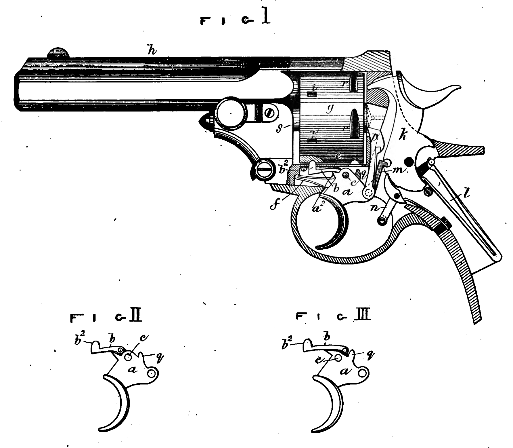
Figure 1 of the accompanying Drawing represents in side elevation (partly in section) a revolving or repeating pistol provided with fixing or locking mechanism constructed according to my Invention.
In the said Figure 1 the locking arm at the front of the head of the trigger a is marked b, the said arm b turning on the same centre c as the trigger a. The cranked or stop end of the locking arm is marked b2, the said stop end working through an opening in the body of the pistol. A light spring e pressing upon the locking arm b near its joint causes it to descend when the trigger is in such a position as to permit it to do so. The downward motion of the locking arm is limited by the shoulder a2 on the head of the trigger a, against which shoulder a1 the trigger spring / bears. g is the revolving cylinder or barrel, and h is the fixed barrel. In the cylindrical surface of the revolving cylinder g is a series of notches or depressions i, in which notches the locking arm 62 engages as herein-after described.
For the purpose of making my Invention the better understood I will briefly describe the parts of the lock mechanism of the pistol, but the said lock mechanism is of the ordinary kind and constitutes no part of my Invention, h is the rebounding hammer, and l is the main spring, the said hammer being lifted into its cocked position by the operation of the arm m jointed to the heel of the trigger; n is the sear for holding the hammer in its cocked position, the said sear being liberated and the hammer allowed to fall by the action of the finger part of the trigger upon the tail of the said sear. The revolving cylinder g is partly turned to bring a fresh chamber opposite the fixed barrel by the operation of the lifter p jointed to the heel of the trigger, and the said revolving cylinder g is locked just before the hammer falls by the stop q on the trigger engaging with one of the notches r in the cylindrical surface of the revolving cylinder.
When the trigger is pressed into its normal position by the trigger spring /, as represented in Figure 1, the stop b2 of the locking arm b takes into one of the notches or depressions i in the revolving cylinder g and locks the said cylinder with one of its charge chambers coincident with the fixed barrel Ji. When the trigger a is pulled to discharge the pistol the locking arm is carried with it, the said locking arm following the downward movement of the trigger by the pressure of the light spring e. The stop end b2 of the locking arm b is thereby withdrawn from the notch i in the revolving cylinder in which it was engaged and the said revolving cylinder is released. The further motion of the trigger causes the arm m to cock the hammer 1c, the lifter p to turn the revolving cylinder sufficiently to bring a fresh charge chamber in a line with the fixed barrel, the stop q to lock the revolving cylinder, and finally, the pistol to be discharged by the finger part of the trigger pressing the sear n. A small antifriction roller may be placed on the sear n to diminish the friction of the finger part of the trigger on the sear.
On relaxing the pressure on the trigger u the several parts return to their normal positions, or the positions represented in the Drawing by the action of the spring/, and the locking arm b, b2, is re-engaged with the revolving cylinder g, and the said cylinder is again fixed or locked.
Instead of jointing the locking arm b to the centre on which the trigger turns, it may have an independent centre as illustrated in Figures 2 and 3. In Figure 2 the locking arm b is centred above and in front of the trigger centre c, while in Figure 3 the said locking arm b is centred above and behind the trigger centre c. I prefer however to use the arrangement shown in Figure 1.
I do not limit myself to the locking arm b on the trigger a taking into notches in the cylindrical surface of the revolving cylinder g, as the said arm may be prolonged and so shaped as to take into notches in the front face of the revolving cylinder or into notches in the hollow axis s on which the said cylinder turns.
Having now described the nature of my Invention, and the manner in which the same is to be performed, I wish it to be understood that 1 claim as my Invention fixing or locking the revolving cylinders or barrels of revolving or repeating small-arms after the discharge of the said small-arms by means of an arm jointed to the head of the trigger taking into one of a series of notches or depressions in the revolving cylinder or in the hollow axis of the revolving cylinder, the said fixing or locking of the revolving cylinder being effected by the returning of the trigger to its normal position, and the releasing of the revolving cylinder being effected by the lifting of the trigger for discharging the gun or pistol, substantially as herein-before described and illustrated in the accompanying Drawing.
In witness whereof, I, the said Charles Pryse, the younger, have hereunto set my hand and seal, this Fourth day of May, in the year of our Lord One thousand eight hundred and seventy-seven.
CHARLES PRYSE, Jun*. (l.s.)
Witness,
Richard Skerrett,
Clerk to George Shaw,
Birmingham.