
US 139461
UNITED STATES PATENT OFFICE.
CHARLES FOEHL, OF PHILADELPHIA, PENNSYLVANIA.
IMPROVEMENT IN REVOLVING FIRE-ARMS.
Specification forming part of Letters Patent No. 139,461, dated June 3, 1873; application filed April 28, 1873.
To all whom it may concern:
Be it known that I, Charles Foehl, of the city of Philadelphia, in the State of Pennsylvania, have invented certain Improvements in Fire-Arms, of which the following is a specification:
My invention relates to revolving fire-arms, and consists in the peculiar construction and arrangement of a ratchet-wheel in the center of the inner end of the revolving chamber, and a spring pawl in the lower part of the hammer, whereby the rotary movement of the cylinder, by the cocking movement of the hammer, is effected in a more simple and reliable manner, and at a less cost in the construction of the same.
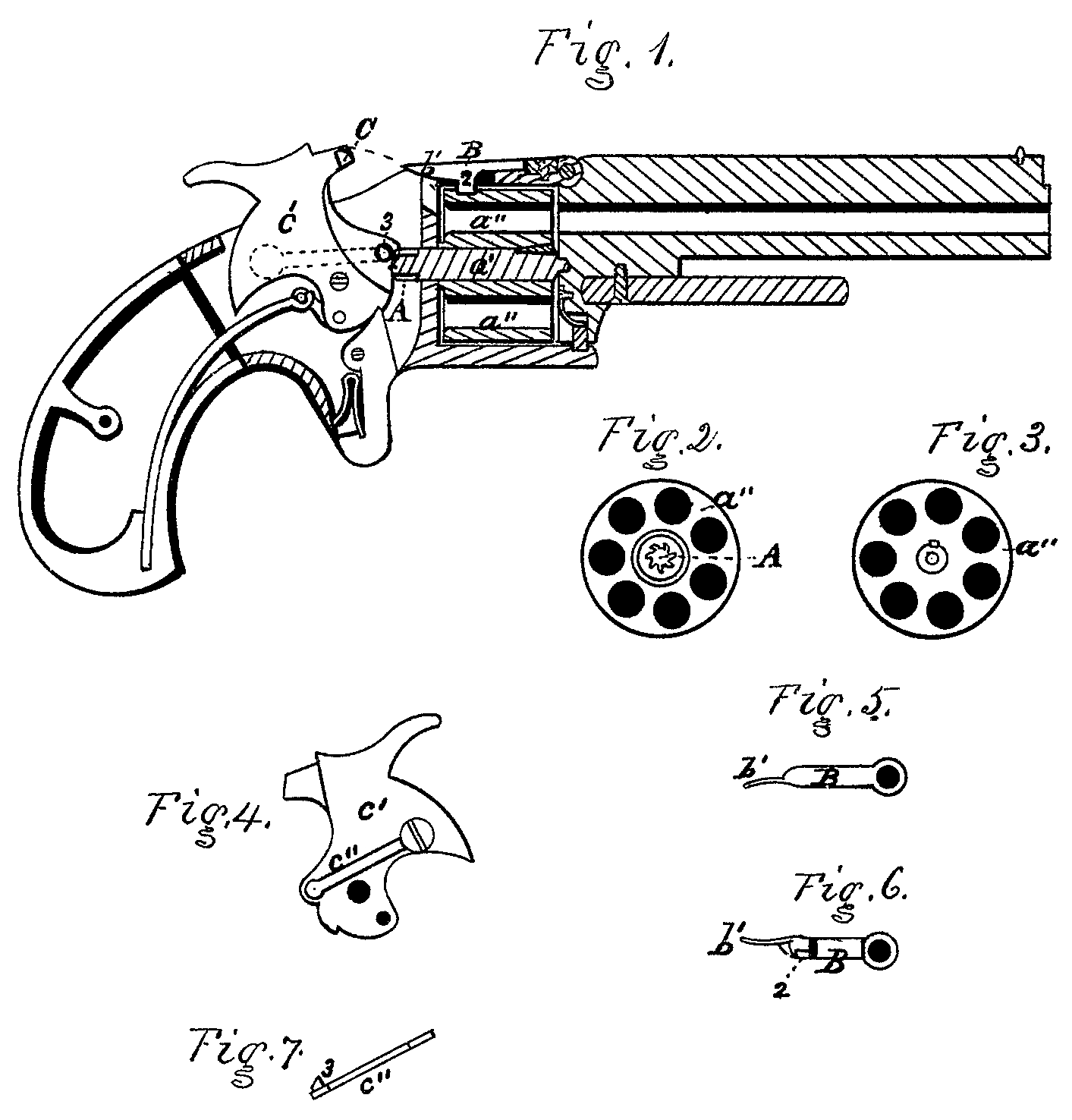
Referring to the drawings, Figure 1 is a vertical longitudinal section of a revolving pistol embodying my invention. Fig. 2 is a plan view of the inner end of the rotary cylinder, with the projecting ratchet-wheel. Fig. 3 is a plan view of the forward end of the rotary cylinder. Fig. 4 is a view of that side of the hammer which is opposite to the side of the same shown in Fig. 1. Fig. 5 is a plan view of the upper side of the spring-pawl which holds the rotary cylinder in its stationary position. Fig. 6 is a plan view of the under side of Fig. 5. Fig. 7 is an edge view of the spring-pawl in the hammer shown in Fig. 4.
The ratchet-wheel A is made on the end of a steel shaft, a’, which forms the central journals upon which the rotary cylinder a” turns. The object in making it separately from the cylinder a” is, that it may be hardened before it is secured firmly in the cylinder as represented in Fig. 1. Around in the perimeter of the cylinder a”, near its inner end, a series of shallow cavities corresponding in position and number with the bores of the cylinder is made, into which the spring-pawl B successively catches as the said cylinder is rotated, and thus holds the latter securely in a fixed position when the fire-arm is cocked and fired. The inner end of the pawl B has a thin springy extension b’, whereby the pawl is lifted to release the cylinder a”, by means of a beveled projection, C, on the side of the nose of the hammer c’; the bevel on the projection C being made so that as the nose of the hammer advances to explode the percussion-cartridge in the cylinder, the said projection will press the springy end b’ of the pawl B aside, and allow the said end to spring back again and catch over the upper part of the projection C, whereby the latter will lift the pawl B when the hammer c is being lifted in cocking, and thus permit the cylinder to be rotated over one space between the cavities into which the pawl’s point or stop 2 enters, as shown in Fig. 1. The spring-pawl c” in the side of the hammer c’, has a beveled projection, 3, which passes through a hole in the hammer c’ with its bevel face downward, so that, as the hammer falls to explode the cartridge, the beveled face of the projection 3, in sliding against the tooth of the ratchet-wheel A yields readily thereto, and after passing the tooth the projection 3, catches under a lower tooth and thereby rotates the cylinder as the said hammer is being drawn backward in cocking.
It will be understood without any further description, that as the nose of the hammer enters the opening to explode the cartridge, the springy end of the pawl B will yield to the lateral pressure of the sloping projection C on the nose of the said hammer, leaving the cylinder a” undisturbed; and that, as the hammer is being drawn back, the projection C will catch under the springy end of the pawl B, and raise it enough to release the cylinder just before the catch of the spring pawl c” in the hammer c’ catches under a tooth of the ratchet-wheel A, and by a continuation of the backward motion given to the hammer rotate the said cylinder the required space, leaving the spring-pawl projection 2 free to drop into the first cavity reaching it.
The construction of the parts described is more simple than any others in use for the same purposes, and, therefore, less costly in the original production, and less likely to get out of order in use.
I claim as my invention—
The spring-pawl c” in the hammer c’, constructed and arranged to operate upon the ratchet-wheel A, substantially as and for the purpose hereinbefore set forth.
CHARLES FOEHL.
Witnesses:
Benj. Morrison,
Wm. H. Morrison.