
US 202613
UNITED STATES PATENT OFFICE.
ROLLIN WHITE, OF LOWELL, MASSACHUSETTS.
IMPROVEMENT IN CHARGING-MAGAZINES AND HOLSTERS FOR REVOLVERS.
Specification forming part of Letters Patent No. 202,613, dated April 16, 1878; application filed March 4, 1878.
To all whom it may concern:
Be it known that I, Rollin White, of and the top of Lowell, in the county of Middlesex and State of Massachusetts, have invented a new and useful Improvement in Magazines for Fire-Arms; and I do hereby declare that the following is a full and exact description of the same, reference being had to the accompanying drawings, and to the letters of reference marked thereon.
The apparatus to be described in this specification is an improvement upon that described in my application filed February 27, 1878, and is designed to be used for the same purposes.
The object of the improvement is a magazine adapted to be carried upon the person, capable of containing a large number of cartridges, and provided with means for charging With a spring action at the same instant such of the chambers of a fire-arm as may be empty, instead of charging all the chambers at the Same time, as in the former application above referred to; also, having a pistol-holster attached to the magazine in such a way that the cylinder may be charged without withdrawing it from the holster.
My invention in the apparatus presently to be described consists, principally, in the such a way that, for convenience in carrying, means by Which the pistol is attached to the magazine; in such a construction of the magazine that the pistol may be charged when it is in the holster, and without removing it; in the means by which all the empty chambers of the cylinder will be charged by a spring action without disturbance of the charges already contained in the cylinder; in the novel construction, arrangement, and combination of the principal operative parts in the magazine, all as more fully hereinafter explained.
In order that those skilled in the art may know how to make and use my apparatus, I now proceed to describe the same in connection with the accompanying drawings, in which—
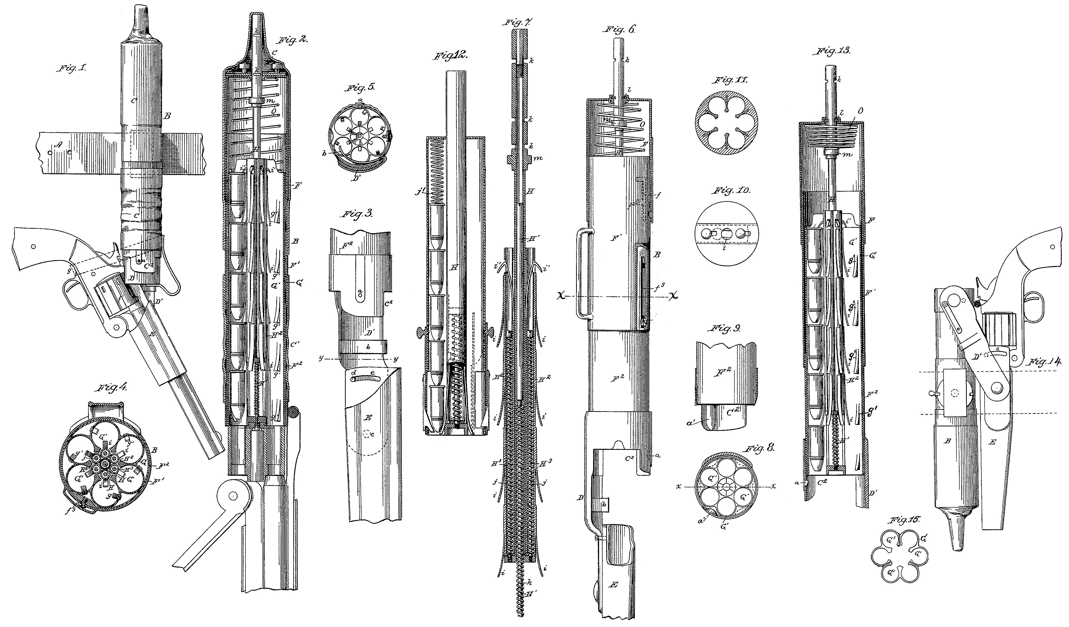
Figure 1 is a side view of my magazine and the holster attached to a belt, with a revolver in the holster in position assumed just before charging the cylinder from the magazine; Fig. 2, a vertical central longitudinal section of the magazine, the cylinder, the holster, and a portion of the barrel of the pistol; Fig. 3, an enlarged view of the bottom of the magazine and the top of the holster; Fig. 4, a cross-section on the line at ac of Fig. 6; Fig. 5, a similar section on the line y y of Fig. 3, looking upward; Fig. 6, a front view of the magazine and holster, with the upper covering-case removed and the top in section; Fig. 7, a vertical central longitudinal section of the plunger; Fig. 8, a cross-section near the mouth of the magazine; Fig. 9, a section on the line x x of Fig. 8; Fig. 10, a top view of the magazine proper; Fig. 11, a cross-section, being a modification in construction of the ammunition-case; Fig. 12, a modification of the ammunition-case, showing separate impelling-springs in each chamber; Fig. 13, a vertical section of the magazine, with the main driving-spring arranged to force out the charges, and showing one chamber unloaded; Fig. 14, a modification of the manner of securing the pistol to the magazine; Fig. 15, a view from above of the top of the ammunition-case of the magazine.
Similar letters denote corresponding parts.
In the drawings, A denotes the belt, to which the magazine B is attached by a swivel-connection, as shown in dotted lines in Fig. 1, in such a way that, for convenience in carrying, the magazine may present itself in a horizontal position, or nearly so; and, when used in the act of charging the pistol, in a vertical position, or nearly so. The magazine, however, may be threaded upon the belt through a loop, as shown in Fig. 6. A cap or cover, C, of any suitable material, protects the upper or inlet part of the magazine from the evil effects of exposure, while another cover, C^1, preferably of suitable flexible material, covers the greater of suitable flexible material, covers the greater portion of the lower part or outlet of the magazine, and to this part is secured a mouth, C^2, preferably of sheet metal. A latch, a, serves to hold the chamber of this cylinder in the proper line for charging, and a suitable plug, D, is held in place by a spring, b. Within this mouth C^2 is a suitable projection, a’, (shown in Figs. 8 and 9,) of a size and form corresponding to the grooves f^1 on the outside of the cylinder, which grooves are preferably extended the whole length of the cylinder.
An extension, D’, of one side of this mouth serves as the means of connection between the magazine and the holster E; but, instead of this extension, there may be a separate strap or link of metal, or of any suitable material, and this strap may be rigidly secured to the magazine or its mouth, or may be secured to either, with any sort of pivot or swivel. The end of this extension, strap, or link D’, however, which is attached to the holster should preferably have a pivotal connection, for convenient operation, one form of which is shown at c in Fig. 3, and, for convenience, should also have means for holding the holster at different angles of inclination, as is shown at d in the same figure, which may be a set-screw working in a curved slot, e, or any other usual contrivance. Upon this extension D’ is shown, in Figs. 3 and 5, a spring, b, whose free point, passing over the outside of the cylinder when it is revolved by hand, or revolving it by direct contact after it has been inserted into the mouth of the magazine, will engage in one of the longitudinal slots f^1 of the cylinder, and hold it in connection with the latch at and projection a’, with its chambers in line with the ammunition-chambers of the magazine.
As constructed and shown in the drawings, the cylinder will be revolved by the action of the spring b alone, and while the cylinder is entering into the mouth C^2 it will be revolved by the spring b in proper position to receive charges from the magazine, and when raised so as to bring the cylinder against the bottom of the magazine, the projection a’ will enter the groove f^1, and hold the cylinder in the proper line for charging.
The holster E, made of any suitable material, and preferably only long enough to give a proper support to the pistol, is suspended or attached to the magazine or its mouth, as described. When the pistol is in the holster, as shown in Fig. 1, it may be secured by any proper strap or elastic band g.
The magazine proper is composed of an outer shell or case, F, made of any suitable material, preferably of sheet metal, in two portions, One of which covers the upper or in let portion of the ammunition-case, and also the upper portion of the other part of the outer shell, F^1, over which it has a telescopic movement; and both parts, F and F^1, have a telescopic movement over the inner shell, to which the flexible character of the cover C^1 offers no impediment. To limit this movement of the part F over the part F, there is a slot, f, upon the outer shell, with a locking notch or notches, in which slot a proper screw or pin, f^2, secured to the outer shell F^1, traverses back and forth, and in like manner the movement of these Outer shells over the inner shell is limited by suitable contrivances f^3.
The inner shell F, which is made of any suitable material, is secured to, or preferably within, the mouth C^2, and may serve as a case for the ammunition-chambers; or these chambers above may be used in lieu of the shell F^2. Upon this shell, as described, or upon the ammunition-case proper, if used as a substitute, the outer shell F F^1, when the two parts are united together, has a telescopic movement, restrained as before described.
Inclosed within the magazine proper, F F^1 F^2, is the ammunition-case G., made of suitable material, and composed of any desirable number of tubes or chambers, G’, arranged around a common center, six in number in the instance shown in the drawings, and of a capacity each to hold five cartridges. From the inner walls of these chambers springs g’ point downwardly, with their free ends projecting inwardly, and are arranged apart about the distance of the length of a cartridge, which Springs Serve to keep the cartridges from upward movement in the chambers, and also to hold the cartridges from dropping out or dropping down out of position.
It is evident, however, that there are many known varieties of detents which would operate in the same way as the springs g’, and are therefore proper equivalents for the same.
The plunger is situated centrally as to the ammunition-chambers, and is composed of a tube, H, having a rod, H^1, to move up and down in its interior, the lower part of the rod having a spiral spring, h, around it. About this tube and rod are tubes H^2 H^2, as many in number as the number of ammunition-chambers G’, which tubes have attached to them springs i i, pointing downward and outward, as many in number as there are cartridges contained in each ammunition-chamber G’ when it is full, and having their points apart the length of a cartridge, which points serve to force down the cartridges against the bases of which they strike.
Hooks i’ i’ serve to hold the upper series of cartridges from moving upwardly, and also to force down the cartridges against which they strike. In each of these tubes H^ H^2 are rods H^3 H^3, having spiral springs j j around them,and these tubes close in at the bottom, and embrace the lower ends of such spiral springs.
In the tube H are scores k k, in which a sliding catch, l, on the top of the outer shell, operates to lock said tube in the desired positions as it passes through said top. Upon the tube is a disk-shoulder, m, upon which the tube is a disk-shoulder, m, upon which the bottom of the main spiral spring O rests, as shown in Fig. 13. If, now, the tube H, being locked in the position shown in Fig. 13, is released from the catch l, the plunger will be thrown down with great force, its springs i i engaging with the bases of the cartridges, and forcing the cartridges contained in the ammunition-chambers into the chambers of the cylinder to be charged. If, however, any chamber of the cylinder is already charged, the cartridge in the ammunition-chamber next above the cartridge in the cylinder will rest against such last-named cartridge, and the tube H^2 forced upwardly the length of a cartridge, and when the plunger is withdrawn the springs j j will return the tubes to position. In brief, these tubes are so arranged to operate with a yielding pressure that their springs force down a cartridge where there is a vacancy to receive it; but when there is no vacancy for the cartridge, then the tube H^2 yields to the pressure, and ceases to force down the cartridge, and thus this plunger will charge only empty chambers in a cylinder, and Will always charge all the empty chambers in such cylinder.
It is evident that the plunger described need not be placed centrally as to the ammunition-tubes, but may be placed on the outside of them.
A modification of the ammunition-case is shown in Fig. 12, wherein the springs i’ i’ on the plunger are all dispensed with, except the lower series in Fig. 7, designed to force down the lowest series of cartridges into the chambers of the cylinder, and the rods. H^3 H^3 and springs j j are dispensed with; but, instead, a spiral spring, j’, is inserted above all the cartridges, which presses them down into proper position; but if every chamber in the cylinder is already charged, then the spring j’ yields to the upward pressure. In this instance an opening for charging at the bottom of the case Will be required, and the plunger-tube will be required to be withdrawn a little in order to let the cartridges down, when the plunger is returned to place by spring or otherwise. Its lower series of springs serve to hold the cartridges from dropping out.
In the modification of the ammunition-case shown in section in Fig. 11, the outer spaces between the shells are shown as filled up with any proper material, or else that the entire case should be made solid out of some proper material, and then bored out. The top of the ammunition-case is illustrated in Fig. 19, in which are shown separate ammunition-tubes, which may be made of hard rubber, gutta-percha, celluloid, or equivalent material, and steel or other proper metal strips separating the tubes, with recesses in them to receive guides attached to the charger; and these tubes may have a metal or gutta-percha or other proper shell around them.
The method of operation of my magazine is as follows, supposing the chambers of the pistol to be unloaded or partially unloaded and the plug D removed: The tube of the plunger is withdrawn and set in position, as shown in Fig. 13, with the mainspring O compressed between the disk on the tube of the plunger and the inside of the top of the magazine, the tube itself being retained in position by the spring-catch in the top of the magazine. The pistol is then inserted into the holster, as shown in Fig. 1. It is opened or broken down by the hand which grasps the pistol, and by a forward movement of the same hand the cylinder of the pistol will be pressed into the mouth of the magazine, the cylinder itself being revolved by the spring b, so that its chambers will be on line with the chambers of the ammunition-case, and raised by the hand until the bottom of the cylinder touches the bottom of the magazine, the projection a’ sliding into the groove f’, and holding the cylinder in the proper position to receive charges from the magazine. In this position of the cylinder it will be held by any suitable spring-catch, as shown in Figs. 6 and 8. The hand then being raised to the top of the magazine, the spring-catch which holds the tube of the plunger is released, the plunger under the impulse of the mainspring flies down, and the lower series of cartridges are forced by the springs of the plunger into the proper chambers. For convenience of, operation, some Well-known attachment may be made to the spring-catch which holds the tube, so that the Same may be operated by the hand in any position along the magazine, or even as it grasps the handle of the pistol. As before explained in the operation of the plunger, only those chambers of the cylinder which are empty will be charged, when the plunger flies down under the impulse of its main spring. The plunger should then be drawn back to its proper position.
Should it, however, be deemed more convenient under any circumstances to operate the plunger directly by manual force, the main spring O is reversed, as shown in Fig. 6, where the body of the spring passes entirely over the disk m on the plunger-tube, and rests upon the top of the ammunition-case. In this in stance the plunger is operated by manual force, as explained in my former application above referred to, and the main spring serves only to return the plunger to its normal position.
After the cylinders are charged, as described, a backward movement of the hand withdraws the cylinder from the mouth of the magazine, a forward movement closes up the pistol, and it is ready to be withdrawn for use.
If it is desired to carry the pistol continually in the holster described, the magazine may be secured vertically, as shown in Fig. 1, and the pistol be carried in the holster below it, for convenience being secured to the magazine by a proper strap or equivalent fastening; or the magazine may be secured upon the belt in a horizontal or nearly horizontal position, and the holster thus be brought up to the belt, or near it, to which it may, if need be, be secured in any convenient Way; or the magazine may be reversed, as shown in Fig. 18, and the holster, which in this instance is attached to the magazine by a connection having a pivot at each end, will be arranged by the side of the magazine, and the pistol will be carried by the side of the magazine, and close to it, and in this position may be secured firmly by any proper strap or equivalent means.
In charging this magazine, it is proper to remove the upper portion of the outer shell, when the cartridges may be inserted by hand in the separate ammunition-tubes until the same are filled; or it can be filled by a charger of my invention, for which I am about to apply for Letters Patent.
It is to be understood that I do not wish to be confined to my description of the various details of construction, since in practice I should endeavor to simplify the same to the fullest extent.
The advantages of my device will be evident upon inspection to those skilled in the business, and, besides, are related generally in the specification to which reference has been made heretofore.
Having thus described my invention, what I claim as new therein, upon which I wish the protection of Letters Patent, is—
1. An independent magazine for charging a revolver, having attached to it a holster, substantially as shown, adapted to hold a pistol, substantially as set forth.
2. An independent magazine for charging a revolver, having a holster attached to it in such a way, substantially as shown, that the cylinder of the pistol may be charged while the pistol is in the holster, substantially as set forth.
3. An independent magazine for charging a revolver, having a holster attached to it in such a way, substantially as shown, that the pistol while in the holster may be secured to the magazine for safe carriage, substantially as set forth.
4. An independent magazine for charging a revolver, adapted to charge at the same time the chambers of the cylinder by a positive spring motion, substantially as set forth.
5. An independent magazine for charging a revolver, adapted to charge all the empty chambers of the cylinder, substantially in the manner set forth, without disturbance of the charges already in such chambers, substantially as set forth.
6. An independent magazine for charging a revolver, having means by which the plunger may be operated by spring-pressure or by hand, as may be desired, substantially as set forth.
This specification signed and witnessed this 4th day of March, 1878.
ROLLIN WHITE.
Witnesses:
L. W. Seely,
A. B. Kelly.