
US 137968
UNITED STATES PATENT OFFICE.
OTIS A. SMITH, OF MIDDLEFIELD, CONNECTICUT.
IMPROVEMENT IN REVOLVING FIRE-ARMS.
Specification forming part of Letters Patent No. 137,968, dated April 15, 1873; application filed September 27, 1872.
To all whom it may concern:
Be it known that I, Otis A. Smith, of Middlefield, in the county of Middlesex and State of Connecticut, have invented a new Improvement in Revolvers; and I do hereby declare the following, when taken in connection with the accompanying drawing and the letters of reference marked thereon, to be a full, clear, and exact description of the same, and which said drawing constitutes a part of this specification, and represents in—
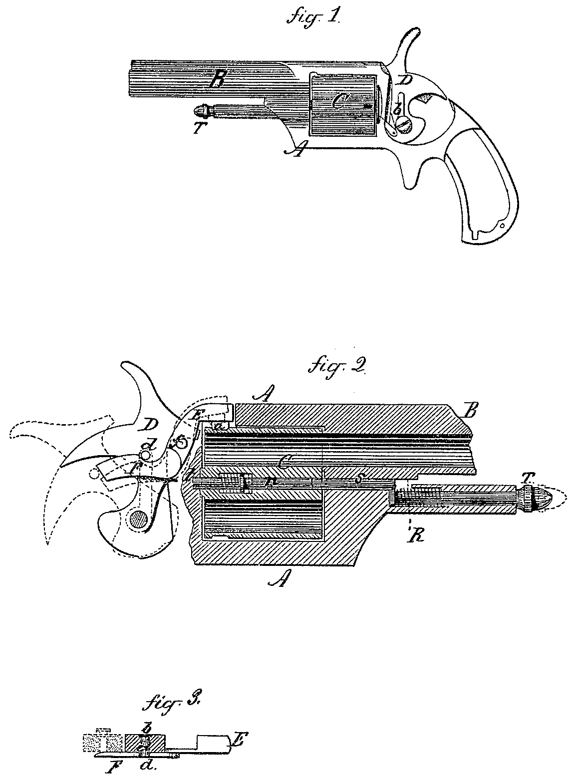
Figure 1 a side view, a portion of the frame removed to show the side of the hammer; in Fig. 2 a longitudinal central section of the barrel and chamber and the reverse side of the hammer; and in Fig. 3 a sectional top view of the hammer and locking-lever.
This invention relates to an improvement in that class of fire-arms which are provided with revolving chambers to receive the ammunition, the object being to lock the chambers in their required position for firing, and prevent the hammer from striking the cartridge until the chamber is so locked; also a convenient device for removing and replacing the cylinder.
The invention consists, first, in combining with the hammer and cylinder a locking-lever, which is raised by the hammer when drawn back for cocking, and from which the hammer escapes and returns for discharge after the said locking-lever has secured the cylinder in the required position; second, in the arrangement of a pintle within the cylinder, and to form the axis of the same, provided with a spring which, when free, will hold the said pintle within the said cylinder, combined with a bolt upon the frame, which, when the cylinder is in position, will, striking the forward end of the pintle, force that back into a seat in the frame at the rear, the said bolt entering the forward end of the cylinder, the said bolt and pintle forming the pivot upon which the cylinder turns, as more fully hereinafter described.
A is the frame; B, the barrel, of common construction, and formed to receive the cylinder C in substantially the usual manner. At one side of the hammer is arranged a lever, EF, pivoted at fin the frame, the arm E extending up over the cylinder and constructed with a downward projection which, when the cylinder is in the proper relative position to the barrel, will rest in a notch in the said cylinder, as in Fig. 2. The other arm, F, of the said lever extends down to one side of the hammer, and upon the hammer is a stud, d, resting above the said lever, as in Fig. 2, and which, owing to the formation of the up per side of the lever, as in Fig. 2, will, when the hammer is drawn back, force down the arm F of the said lever, raising the arm E, as denoted in broken lines, Fig. 2, until the said stud passes off or escapes from the lever, as denoted in broken lines. In the act of drawing back the hammer the cylinder is rotated, bringing a second chamber in line with the barrel in the usual manner; the lever falling, as before described, locks the chamber in that position. The stud d extends through the hammer, as seen in Fig. 3, and is provided with a spring, b, upon the opposite side, as in Fig. 1. The end of the arm F on the side next the hammer is inclined, as seen in Fig. 3, so that as the hammer returns after the lever has locked the cylinder the stud passes over the incline, being thereby forced into the hammer, as denoted in Fig. 3; therefore, on its return having no effect upon the lever; but so soon as the hammer arrives at its home position the bolt is thrown out above the lever as in Fig. 2, preparatory to operating the lever, as before described, when the hammer is again drawn back. The nose of the hammer is fitted to the said lever so that, unless the lever be dropped into the notch in the cylinder, the hammer cannot strike the cartridge; hence the cartridge cannot be exploded until in proper relative position to the barrel. Centrally in the cylinder C is arranged a pintle, n, of nearly or exactly the length of the cylinder, provided with a spring, as seen in Fig. 2, the tendency of which is to hold the said pintle entirely within the cylinder. In the frame at the rear a recess or seat, t, is made corresponding to the end of the said pintle, so that when the cylinder is in proper position the pintle may be forced back into the said seat, as seen in Fig. 2. Upon the frame beneath the barrel a bolt, s, is arranged in a line with the said pintle and provided with means, or a suitable head, T, by which the said bolt may be drawn forward, as denoted in broken lines. Upon the said bolt a spring, R, is arranged, the tendency of which is to hold the bolt into the frame so that the end of the bolt will extend within the cylinder, as in Fig. 2, bearing against the forward end of the pintle, the spring R being sufficient to overcome the spring on the pintle and force the pintle back into its seat on the frame. Thus the pintle and bolt combined form the two bearings— that is, respectively, the rear and front— upon which the cylinder will turn.
To remove the cylinder, draw the bolt s forward from the cylinder, as denoted in broken lines. The pintle will by the reaction of its spring be drawn into the cylinder and thus leave the cylinder free to be removed. Replaced again the bolt returns and forces the pintle into its seat, as before described.
I claim as my invention—
1. In combination with the hammer D and cylinder C, the lever E F and the stud d upon the hammer, operating together to release and lock the cylinder, substantially as set forth.
2. In combination with the cylinder C and its frame, the pintle n axially within the cylinder, and the bolts in the frame, the said bolt and pintle together forming the axis upon which the cylinder turns, substantially as set forth.
OTIS A. SMITE.
Witnesses:
E. B. Savage,
M. D. Andrus.