
US 22511
UNITED STATES PATENT OFFICE.
C. S. PETTENGILL, OF NEW HAVEN, CONNECTICUT.
IMPROVEMENT IN REVOVING FIRE-ARMS.
Specification forming part of Letters Patent No. 22,511, dated January 4, 1859.
To all whom it may concern:
Be it known that I, C. S. Pettengill, of the city and county of New Haven, and State of Connecticut, have invented certain new and useful improvements in that class of fire-arms known as “Revolvers;” and I do hereby declare that the following is a full, clear, and exact description of the same, reference being had to the accompanying drawings, forming part of this specification, in which—
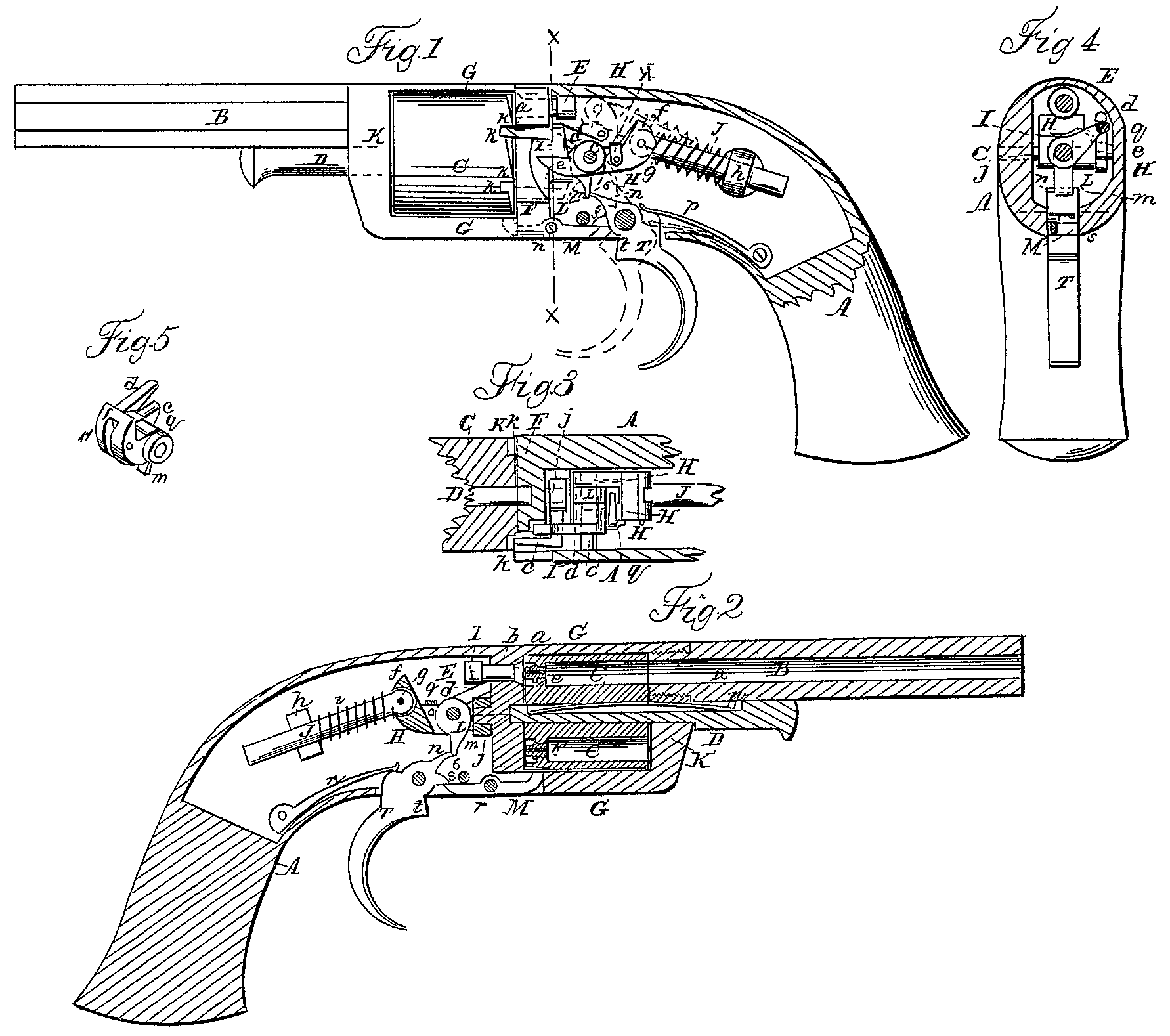
Figure 1 is a side view of a pistol with one side of the stock broken away to expose the lock, the latter being shown cocked. Fig. 2 is central longitudinal section of the same, looking sidewise. Fig. 3 exhibits a top view of the interior of the lock with parts of the stock and cylinder in section. Fig. 4 is a transverse section in the line x x of Fig. 1. Fig. 5 is a perspective view of the tumbler detached.
Similar letters of reference indicate corresponding parts in the several figures.
This invention relates to that kind of revolver which is in most common use, having its chambered cylinder arranged to rotate on its axis parallel with the bore of the barrel.
It consists in certain novel combinations and arrangements of parts of the lock for the purpose of effecting the cocking of the hammer, the rotation of the cylinder, and the locking of the cylinder with its chambers in position for firing all by the movement of the trigger.
To enable others skilled in the art to make and use my invention, I will proceed to describe its construction and operation.
A FG K is the stock of the pistol, having the barrel B attached in the ordinary manner.
C is the rotating chambered cylinder, fitted to rotate on a central pin, D, which is secured in the stock by a friction-spring, u, applied in a slot, v, in its upper side, and a pin, w, attached to the barrel, said cylinder being fitted within a breech-frame, F G. K, of the usual form, constituting part of the stock.
E is a percussion-pin to be operated upon by the hammer f to explode the caps or their percussion priming, said pin Working in line with the axis of the barrel through a guide in the breech-supporter F, and having the front part made with a conical head or to fit into a conical seat in the breech-supporter in front of its guide b, and constitute a valve to exclude from the lock the gases and smoke resulting from the explosion of the percussion-caps, said valve being closed by the force of the explosion of the cap, which forces back the percussion-pin E.
His the tumbler of the lock, working on a fixed pin, O, which is inserted transversely through the stock, and occupies about the same position in the lock as the pin upon which the hammer usually works, said tumbler being made with a fork, d e, to embrace and operate the bent dog I, by which the cylinder is rotated, and with a long heel, f, which constitutes the hammer, and to which is jointed by a pin, g, a sliding bolt, J, which works through a fixed guide, h. i is the mainspring, coiled round the bolt g between the guide h and the hammer f.
The bent dog I, above mentioned, for rotating the breech, is fitted to turn on a fixed conical projection or stud, j, at the back of the breech-supporter opposite the center of the cylinder, and its tooth engages with a series of ratchet-like notches, k k, in the rear of and near the periphery of the cylinder. The said dog is not confined upon the stud j, so as to be incapable of at any time moving back upon it, but is left free to move back a little way to allow its tooth to pass out of the ratchet-notches k k as the said dog is caused to move back by the movement of the tumbler which gives the blow of the hammer. The said dog is, however, forced into and held in the ratchet-notches during the cocking movement by a cam, L, twining on the pin c, and by that means is caused to effect the rotation of the cylinder by the movement it derives from the fork d e in the act of cocking. A very slight backward movement of the dog on its stud j is, owing to the conical form of the stud, sufficient to permit the dog to work free of the teeth in going back.
The said calm L also serves to combine the trigger T with the tumbler H to effect the cocking, and for this purpose is fitted in a slot in the tumbler, and made with a tail, m, to operate in combination with a horn, n, on the trigger, and with an inclined projection, o, at the back to act against a corresponding inclined surface on the tumbler. The cocking is effected by pulling back the trigger, which brings the horn n of the latter into operation on the back of the tail m of the cam, and, forcing the said tail forward, drives back the projection o against the tumbler, and throws back the tail of the latter until the point of the horn n enters a very slight notch, 6, in the said tail. When the horn n falls into this notch the said horn and the tail m have arrived at such positions that their pressure against each other, caused by the mainspring i and trigger-spring p, causes them to hold each other stationary. The dropping of the horn into the notch 6 will be very perceptible to the touch of the operator, who may, when the arm is cocked, refrain from firing till a convenient time, when by drawing back the trigger a little farther its horn will be caused to pass the tail m and leave the tumbler under the control of the mainspring, which will instantly drive the hammer forward against the percussion-pin E, and cause the latter to be driven forward against the cap, or such percussion priming as may be used, with sufficient force to explode it.
The cam L might be dispensed with, and its tail m and the portion which acts on the dog I be made portions of the tumbler but for the necessity of horn n of the trigger passing the tail m as the trigger moves forward when released by the operator’s finger after the arm has been fired, and to provide for that it is made separate and a spring, 9, is applied to press upon the top of its rearward projection, o, to bring it back to a proper operative position after it has moved out of the way to let the trigger-horn pass it as the trigger moves forward.
The arm may be fired without letting the parts rest cocked, as in the above-described operation, by drawing the trigger all the way back at once, so that the horn of the trigger will not rest in the notch 6; or after it has been cocked it may be uncocked without firing by pressing the trigger forward till its horn moves out of the notch, and then only permitting it to move forward very gradually, so as to prevent the sudden and violent movement of the tumbler and hammer which is necessary to explode the cap or priming.
M is a locking-lever arranged to work upon a pin, r, in the bottom of the stock and in rear of the cylinder. The front extremity of this lever is turned up, so as to enable it to enter a series of secondary notches, k’ k’, made in the bottoms of ratchet-notches k k. The front end of the said lever is thrown up, so as just to enter into the notches k’ k’ as the cocking operation is completed, by the depression of its rear end by a horn, s, on the trigger, which then comes into operation on it, and it enters deeper there into as the trigger is moved beyond that position to fire the piece, and hence is caused to lock the cylinder very securely. The said locking-lever is thrown out of the notches when the trigger is not cocked by the action underneath its rear end of a projection, t, on the trigger, as is illustrated by the red outline in Fig. 4.
gy is a pin which serves as a stop to the locking-lever, and also to the trigger when the latter is not cocked.
What I claim as my invention, and desire to secure by Letters Patent, is—
1. Combining the hammer and the rotating dog with the trigger by means of a forked tumbler, H, and a cam, L, working on the same pin, the said cam being formed with a notched tail, m, to engage and operate in combination with a horn on the trigger, substantially as and for the purpose set forth.
2. The bent dog I, applied, as described, on a fixed conical stud on the center of the rear of the breach-supporter, and combined with a cam, L, on the tumbler-pin c, to operate substantially as described.
3. The arrangement of the helical mainspring upon a bolt which is jointed to the hammer, and which slides through a fixed guide in the rear thereof, substantially as herein described.
C. S. PETTENGILL.
Witnesses:
R. Reed,
O. D. Munn.