
US 22666
UNITED STATES PATENT OFFICE.
H. S. NORTH OF MIDDLETON, AND E. SAVAGE, OF CROMWELL CONN.
IMPROVEMENT IN REVOVING FIRE-ARMS.
Specification forming part of Letters Patent No. 22,666, dated January is, 1559.
To all whom it may concern:
Be it known that we, Henry S. North, of Middleton, in the county of Middlesex and State of Connecticut, and Edward Savage, of Cromwell, in the same county and State, have invented certain new and useful Improvements in Revolving Fire-Arms; and we do hereby declare that the following is a full, clear, and exact description of the sane, reference being had to the accompanying drawings, forming part of this specification, in which—
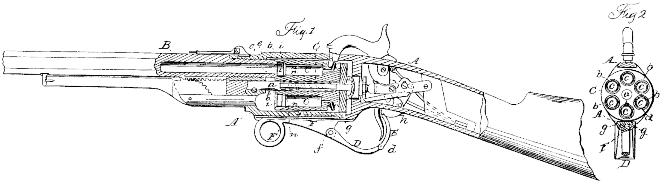
Figure 1 is a longitudinal central sectional view of a rifle with our improvement. Fig. 2 is a transverse section of the same just in front of the cylinder.
Similar letters of reference indicate corresponding parts in both figures.
Our invention relates to that class of revolving fire-arms in which the many-chambered cylinder rotates upon an axis parallel with the bore of the barrel.
One feature of our invention consists in the employment of movable cylindrical bushings or thimbles fitted in to cavities formed around the front portions of the chambers of the rotating cylinder in such a manner as to fit to an external seat at the rear end of the barrel while the latter enters within the chambers, and as to allow the gases resulting from the explosion of the charge to act upon their rear ends to drive them forward against the barrel and make them form close joints there with for the purpose of preventing the escape of fire or gas.
Another feature of our invention consists in the combination of a slide fitted to work longitudinally under the cylinder-frame, and a jointed trigger-guard, part of which also constitutes a part of a lever for effecting the operations of rotating and locking the chambered cylinder aid of cocking the lock, such combination being for the purpose of preventing the mechanism by which the above-mentioned operations are effected from incumbering the exterior of the piece in any of its conditions, and allowing such mechanism to be operated by the left hand to repeat the fire without removing the piece from the shoulder or even disturbing the aim.
To enable those skilled in the art to make and use our invention, we will proceed to describe its construction and operation.
A is the frame, which contains the rotating many-chambered cylinder C and the lock, and which forms the connection between the stock S and barrel B. The cylinder C is fitted to rotate on a fixed arbor, a, and besides its rotary motion it has a motion parallel with its axis for the purpose of bringing it up to the barrel before firing, and after wall drawing it back clear of the barrel to permit its rotation.
b, b are the cylindrical bushings or thimbles, whose application within the chambers c c constitutes the first-mentioned feature of our invention. These bushings or thimbles may the made of steel or other metal, and have their bore as large or very slightly larger than the general size of the bore of the chambers c c. Their thickness may be about one-twentieth (1/20) of an inch and their depth about three-sixteenths (3/16) of an inch. The mouths of the chambers c c are bored out to a depth somewhat greater than the depth of said bushings or thimbles to form cavities large enough to receive said bushings or thimbles within them, as shown at i i, in Fig. 1, the said bushings or thimbles fitting so snugly into the so-enlarged portions i i of the chambers as to prevent the escape between them of the gases resulting from the explosion, and having portions n n of the cavities unfilled behind them, into which the gases resulting from the explosion of the charge can enter to act upon the rear ends of the said bushings or thimbles to press the in closely against the rear of the barrel for the purpose of preventing any escape between the cylinder and barrel. To provide for the operation of these bushings or thimbles, it is desirable that the valve-like face or seat e e at the end of the barrel shall enter the chambers when the joints between the chambers and barrel are closed; and to permit thistle cylinder requires to have a movement longitudinally or in a direction parallel with its axis, as before mentioned, as well as a rotary movement. This longitudinal movement is effected in the example of the invention represented in the drawings by the toggle-connection between the cylinder or recoil-shield and stock, which forms part of the subject-matter of Letters Patent granted to the within-named Henry S. North, dated June 17, 1856; but other meals of producing said movement might be adopted.
D E is the trigger-guard, made in two pieces, collected by a joint at d, and being connected at the front bed-joint, f, (see Fig. 1) to the side F, which is fitted to slide longitudinally lack and fort l in a groove, g, in the bottom of the frame A, and which is provided with a ring, F’, to enable it to be laid hold of with the left had while the piece is held at the shoulder in position for firing. The rear position, E, of the trigger-guard constitutes at portion of a lever, which works on a fulcrum-pill, h, for the purpose of operating the mechanism by which the rotary and longitudinal movements of the cylinder and the cocking of the hammer are effected. This lever is like the finger-lever described in the aforesaid Letters latent of Henry S. North for the purpose of effecting the same movements. By pulling back the slide F the lower end of the lever E is moved back, and the operations of drawing back or unlocking and rotating the cylinder and of cocking the hammer are effected, and by pushing forward the said slide again the lever E is caused to act upon the toggle-connection to force forward and lock the cylinder and barrel.
The above-described combination of the sliding piece F’ and jointed trigger-guard may be applied in combination with a lever operating through any other agency to effect the locking and rotation of the cylinder and cocking of the hammer with great advantage, as the slide F’, from its position and arrangement, call be operated by the left hand to repeat the fire without relinquishing the support which the said hand gives to the piece— rifle, fowling-piece, musket, or carbine— while held to the right shoulder or disturbing the arm.
We are aware that many applications of lacking-rings or thimbles have been made to breech-loading fire-arms to le acted upon by the force of the explosion to close the joints between the chamber and breech, and that application has been made to fire at its of the same kind of a thimble to be acted upon by similar agency to close a joint between the chamber and barrel. We therefore disclaim entirely the use of rigs or thimbles whet not applied, as herein described, in combination with a rotating chambered cylinder having also a longitudinal movement; but
What we claim as our invention, and desire to secure by Letters latent, is—
1. The employment of the movable cylindrical bushings or thimbles b b, applied, substantially as herein described, within cavities i i, formed in the front portions of the chambers of a rotating chambered breech which has a longitudinal movement to operate and be operated upon, substantially as herein specified, in combination with a valve-like seat, c e, which is formed upon the rear of the barrel.
2. The combination of the slide F, working it the bottom of the cylinder-frame A, and the double-jointed trigger-guard D E, part of which constitutes also a part of a lever through whose agency the rotation of the cylinder and cocking of the hammer are effected, the whole operating substantially as and for the purpose herein specified.
HENRY S. NORTH.
EDW. SAVAGE.
Witnesses:
Arthur. B. Calef,
Jonathan Barnes,