
US 306596
UNITED STATES PATENT OFFICE.
CARL J. EHBETS, OF HARTFORD, CONNECTICUT, ASSIGNOR TO THE COLTS PATENT FIRE ARMS MANUFACTURING COMPANY, OF SAME PLACE.
LOCK FOR FIRE-ARMS.
SPECIFICATION forming part of Letters Patent No. 306,596, dated October 14, 1884.
Application filed June 23, 1884. (No model.)
To all whom it may concern:
Be it known that I, CARL J. EHBETS, of Hartford, in the county of Hartford and State of Connecticut, have invented new Improvements in Revolvers; and I do hereby declare the following, when taken in connection with accompanying drawings and the letters of reference marked thereon, to be a full, clear, and exact description of the same, and which said drawings constitute part of this specification and represent, in–
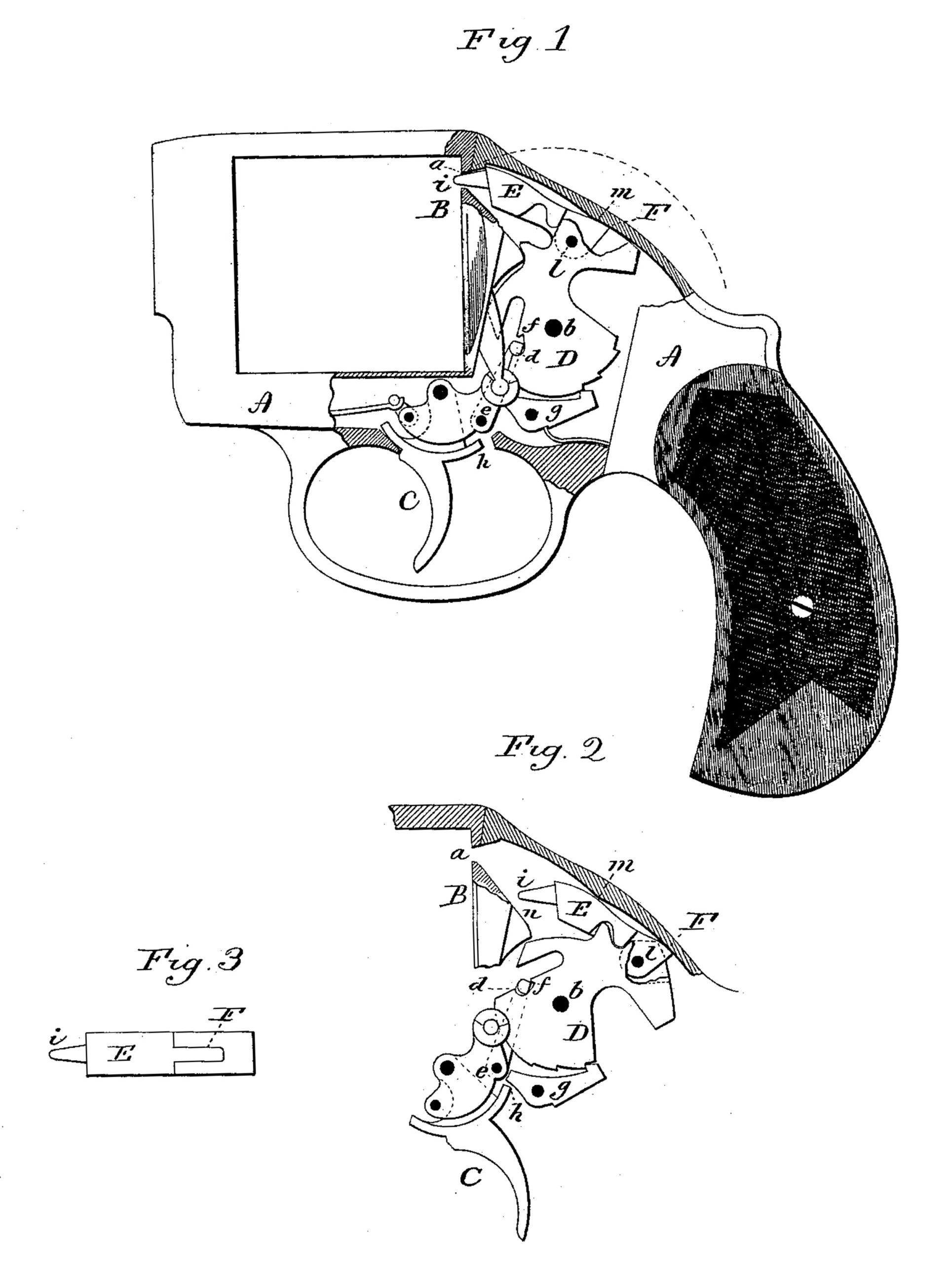
Figure 1, a sectional side view of so much of a revolver as will illustrate the invention, and showing the hammer in its forward position; Fig. 2, same side view, showing the hammer in its extreme rear position; Fig. 3, top view, looking down upon the hammer and showing the hinge-joint between the nose and body portion.
This invention relates to an improvement in revolving fire-arms, with special reference to the hammer. In the more general construction of revolvers, the hammer extends up through the frame, and is provided with a thumb-piece, by which, if occasion requires, the hammer may be turned. Accidents frequently occur in the use of these arms, due chiefly to the exposure of this projecting part of the hammer. If in the usual construction of hammer the thumb piece or extension be dispensed with it is impractical to inclose the hammer within the frame–as, for illustration, the arc described by the nose of the hammer. turning upon its pivot would be as indicated in broken line, Fig. 1. To increase the extent of the frame so as to permit this arc to be described within it would not only make the frame cumbersome, but would detract materially from the graceful appearance of the arm.
The object of my invention is to conceal the hammer and yet permit it to swing upon its pivot in the usual manner; and it consists in constructing the hammer in two parts–a body portion and nose portion–the nose part hinged to the body portion of the hammer, so that the nose may turn upon its hinge in a plane at right angles to the pivot on which the hammer turns, said hammer constructed with an extension in rear of its hinge and a bearing in the frame above the nose-piece, serving to direct the nose of the hinged portion in its forward movement, as more fully hereinafter described.
A represents the frame of the revolver in the usual shape, except that, instead of the recess within which the operative mechanism is arranged being open at the top, the top of the recess is closed.
B represents the usual recoil-plate, in which is an opening, a, through which the nose of the hammer may pass to strike the cartridge; C, the trigger; D, the body of the hammer hung upon a pivot, b, in the usual method of hanging the hammer of revolvers. The hammer is turned rearward upon its pivot by means of the trigger, which may be connected with the hammer by any of the usual mechanism for so doing, such mechanism constituting no part of my present invention.
As illustrated, the hammer is turned by means of a strut, d, hinged to the trigger, as at e, and in rear of the pivot of the trigger, the upper end or nose of the said strut arranged to engage a notch, f, on the hammer forward of its pivot, whereby when the trigger is pulled the hammer is thrown rearward until such time as the strut may escape from the notch; then the hammer will fly forward under the reaction of the main spring unless a sear, g, or its equivalent, be a ranged to engage a notch on the hub of the hammer, say, when at full-cock, as seen in Fig. 2, which engagement occurs just before the strut d would escape from the notch f of the hammer. In such case the trigger is constructed with a shoulder, h, which, when the trigger is further pulled, will strike the seal and turn it from its engagement with the hammer, so that the hammer will escape and be thrown forward under the reaction of the mainspring.
Instead of making the hammer in a single piece throughout, the nose portion E is made separate from the body, hinged thereto above the pivot of the hammer and as at l, and so as to swing on its pivot in a plane at right angles to the axis or pivot on which the hammer turns, the nose being free to swing upon its hinge l and so as to be turned from its forward position, as seen in Fig. 1, to the position of full-cock, as seen in Fig. 2, approaching the pivot of the hammer as the hammer is thrown rearward. This movement contracts the extent of the hammer–that is, the radius from the nose to the pivot of the hammer is contracted by so much as the nose portion is turned toward or approaches the pivot of the hammer. The nose is provided with the usual point, i, to pass through the aperture a in the recoil-plate to strike the cartridge, and has an extension, F, in rear of its pivot.
The top of the recess in which the hammer works is constructed to form a bearing, m, against which, when the hammer is in its forward position, the extension F of the hammer will rest, and in so resting the nose of the hammer is thrown up to its proper striking-position and there held.
From the bearing-point m in the top of the recess the surface inclines from or is made eccentric to the pivot b of the hammer, and so that as the hammer is turned backward the projection F may turn outward to permit the nose portion to turn downward, the back of the nose portion riding over the bearing m to cause it to thus turn, and the curvature of the top of the recess in rear of the bearing m should be made so that the projection F may ride thereon, while the back of the nose-piece rides upon the bearing-point m, and so that the nose-piece will be supported by the two points, one in the rear and the other forward of its hinge, and thereby be prevented from play. When the hammer has been thrown back to full-cock, as seen in Fig. 2, the nose is far below the aperture through which it is to strike. As the hammer escapes from the strut or from the sear, as the case maybe, under the reaction of the mainspring, it is thrown forward in the usual manner, and in such movement the extension F rides upon the upper surface of the recess and causes the nose of the hammer to turn forward, until arriving at its extreme forward position it has reached the bearing m and the hammer is in its proper position to strike the blow. The connection between the nose-piece and the body is simply tongues on the one setting into a groove in the other, as seen in Fig. 3. The shoulder on the tongue part should take a bearing on the corresponding edge of the other part, so as to form a strong support or connection between the two in imparting the blow.
While I prefer to govern the movement of the nose portion of the hammer by the top of the recess in the frame, the nose may be guided in its forward movement by the bottom n of the passage to the aperture i, the bottom of this passage being inclined upward and forward toward the aperture, as shown, and so that the point of the hammer may strike this inclined surface as the hammer is forced forward and ride up thereon, and so as to pass through the aperture.
It will be readily understood that in the class of revolvers in which a firing-pin is employed against which the hammer strikes, the point on the nose of the hammer in this case will be dispensed with, the hinged portion striking the firing-pin as does the hammer in the usual construction. In fact, the operation of the hammer is precisely the same as that of the hammer of usual construction, save only that the nose portion is hinged to permit it to approach the pivot on which the hammer turns in its rear movement, and recede therefrom as it is thrown forward.
I have described and illustrated my invention as applied to a revolver, and it is to this class of fire-arms to which my invention is particularly adapted; but it may be applied to other arms in which a concealed hammer is desirable.
I claim–
The combination of the body portion D, and the nose portion E, hinged thereto above the pivot on which the hammer turns, and so as to swing in a plane at right angles to the pivot on which the hammer turns, the said nose piece constructed with an extension, F, in rear of its hinge-pivot, the recess in the frame constructed with a bearing, m, above the nose-piece, and in rear of the hinge-pivot when the hammer is in its forward position, and against which the extension F will strike, with mechanism substantially such as described, to turn the said hammer upon its pivot, substantially as specified.
CARL J. EHBETS.
Witnesses:
HORACE LORD,
EDWD. J. MURPHY.