
US 306276
UNITED STATES PATENT OFFICE.
JOHN HENRY MUNCH, OF SAN ANTONIO, TEXAS.
CHARGER FOR LOADING REVOLVERS.
Specification forming part of Letters Patent No. 306,276, dated October 7, 1884.
Application filed March 17, 1884. (No model.)
To all whom it may concern:
Be it known that I, JOHN HENRY MUNCH, of San Antonio, in the county of Bexar and State of Texas, have invented a new and Improved Charger for Loading Revolvers, of which the following is a full, clear, and exact description.
My invention consists of a cylindrical case of metal, pasteboard, or other suitable material, contrived with a center piece, by which a number of cartridges corresponding to the number of chambers in the cylinder of the fire-arm may be located in the charger suitably for being simultaneously entered at the points in the chambers of the cylinder and be discharged from the charger into the cylinder all at once, to facilitate the loading of revolving fire-arms, all as hereinafter fully described.
Reference is to be had to the accompanying drawings, forming part of this specification, in which similar letters of reference indicate corresponding parts in all the figures.
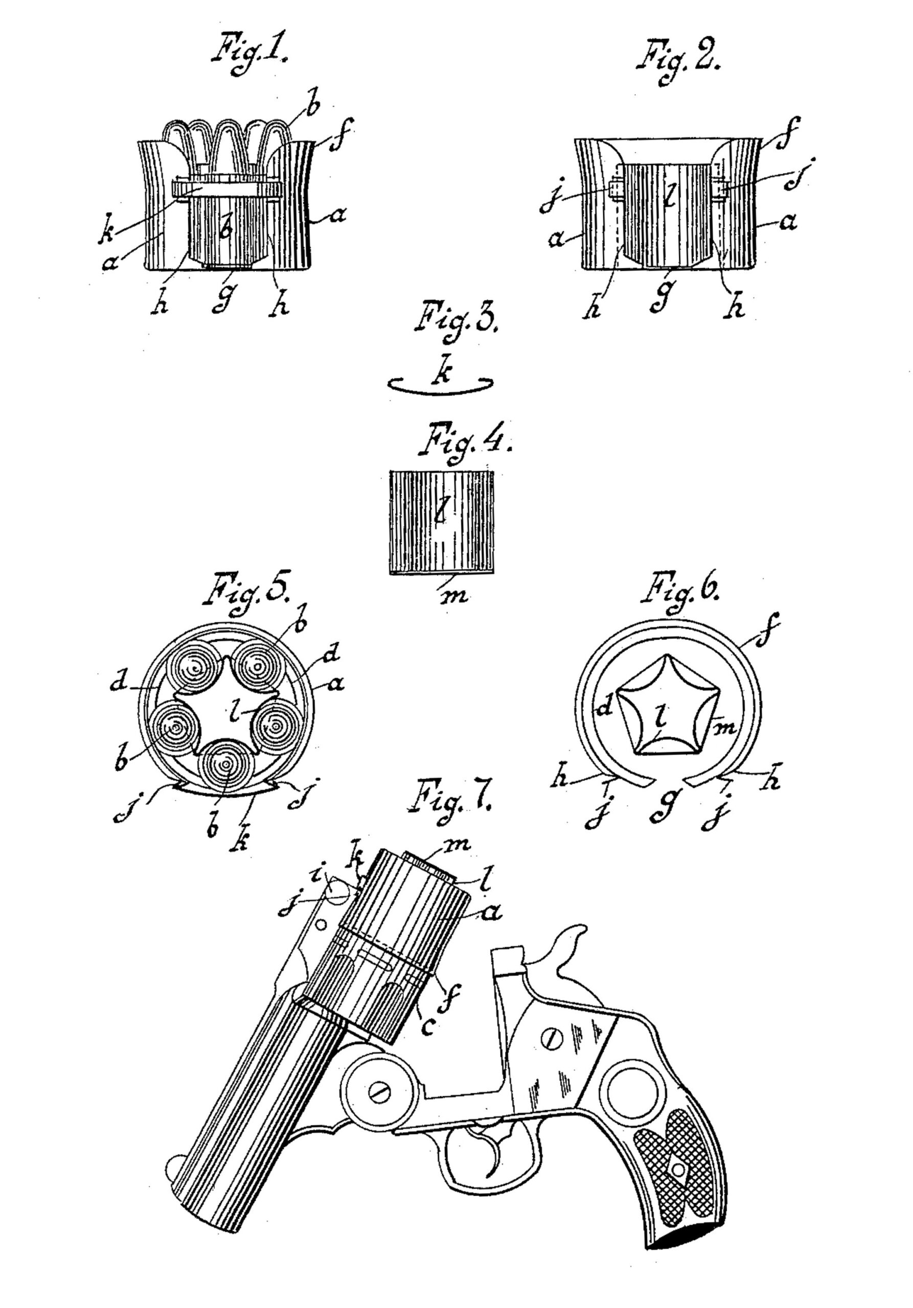
Figure 1 is a side elevation of my improved charger, with the complement of cartridges ready for charging into the cylinder of the revolver. Fig. 2 is a side elevation of the empty charger. Fig. 3 is a top view of a clasp employed to bind the cartridges in the charger preparatory to charging them into the cylinder of the revolver. Fig. 4 is a side elevation of the center piece employed for locating the cartridges in the charger. Fig. 5 is a top or plan view of the charger and its charge of cartridges. Fig. 6 is a top or plan view of the empty charger. Fig. 7 is a side elevation of a revolver, with the charger applied as in the act of charging the cartridges into the cylinder.
I make a band or ring, a, for the shell or case of the charger of thin sheet metal, pasteboard, or other suitable material, about as wide as the length of a cartridge, b, and about as large in diameter as the diameter of the cylinder c of the revolver to be charged, with a flange, d, turned inward at one end, also with the other end flared outward at f, and also with an open space, g, between the ends h of the band, about as wide as the lever i of the revolver, and I make a hook-flange, j, on each end of the band a, to connect said ends by a clasp-hook, k, as shown in Figs. 1 and 5. Together with this case I make a core-piece, consisting of the fluted ring l and the flange-head m, the flutes being arranged in size, number, and position to locate the cartridges b so that they will be coincident with the chambers of the cylinder c to be loaded when the charger is presented to the cylinder, as represented in Fig. 7. The cartridges are placed in the charger. with their heads resting on the flanges d and m, one in each of the flutes of the ring l. After placing the cartridges in the charger, the ends h of the band are hooked together by the clasp k which springs the upper or flanged side of the ring together a little, so as to contract the space sufficiently to prevent the escape of the cartridges by falling out in case the charger is inverted, by binding the flanges of the cartridges between the ring at and the fluted ring l. The charger thus loaded is to be presented to the open end of the cylinder c of a Smith and Wesson or other like revolver when the cylinder is lifted up, as represented in Fig. 7, and pressed thereon, so that the flaring end f passes down over the cylinder, the ring being placed with the opening g in range of the lever i of the revolver, so that the ring will not be obstructed by it. The flange d then pushes the cartridges into the cylinder, and the end of the core l m stops against the end of the cylinder, so that the cartridges are pushed from said core, which, passing through the ring, drops out. The clasp-hook k is pushed from the hooks j by the end of the lever i, so as to permit the case to be pushed far enough onto the cylinder to push the cartridges home in the chambers. The case is then pulled off, ready for being filled again, and the barrel is adjusted for firing.
The core for locating the cartridges in the go case will have as many flutes as there are chambers in the cylinder to be charged, and said flutes will be made to correspond in size with the caliber of the cartridges and the chambers to be charged.
By using cores of different sizes for different calibers, and clasp-hooks k of different sizes, the shell or case a may serve for cartridges of different calibers by being sprung together more or less at the ends.
This improved charger will be found very useful in economizing time by being charged beforehand, so that all the cartridges may be quickly thrust into the cylinders at once, and it will be particularly useful in cold weather, when it is difficult to handle the cartridges singly by the cold and stiffened fingers.
Having thus described my invention, I claim as new and desire to secure by Letters Patent
1. An improved charger consisting, essentially, of a split band provided with an in. ward-projecting flange for supporting the cartridge-head, a core within the band, and a clasp for connecting the split edges of the band, whereby the cartridges may be clamped between the core and the band and released by removing the clasp, substantially as set forth.
2. The combination of the split band a, provided with an inward-projecting flange, d, and a hook, j, on either side of the opening, as shown, with the fluted core l, provided with a flange, m, and the clasp k, for securing the cartridges between the core and band, and constructed to be displaced vertically, substantially as and for the purpose set forth.
3. The combination of the center piece, consisting of fluted ring l and flange-head m, with the shell, consisting of band a, having flange d, hooks j, and flaring end f, and provided with the hook-clasp k, substantially as described.
JOHN HENRY MUNCH.
Witnesses:
C. H. CLIFFORD,
J. C. TUCKER.