
Britain 5778
A.D. 1888, 18h April. № 5778.
PROVISIONAL SPECIFICATION.
Improvements in Repeater and other Small Arms.
We, John Carter of Mona Terrace, Bracebridge Street, Aston Juxta, Birmingham, in the County of Warwick, Pistol Action Filer, and William John Whiting also of Mona Terrace, Bracebridge Street, Aston Juxta, aforesaid, Tool Maker, do hereby declare the nature of this invention to be as follows:—
This invention relates to repeater, and other small arms; and consists 1st, in raising or rebounding the hammer to full cock, by the return movement of the trigger, after firing. 2ndly, in locking the chambered cylinder, of a repeater small arm, at two points, instead of at one, as is now commonly done. 3rdly, making the top limb of the main spring, act as a sear, as well as a means for the throwing forward of the hammer, on the discharge of the arm. 4thly, means for operating the second cylinder stop, which constitutes the second arrangement for locking. 5thly, making the free end of the stand or bottom side of the main spring, press upon the flat of the leg of the lifter, by means of which lifter, a semi-rotation is given to the chambered cylinder, on the pulling of the trigger.
We will first describe our invention, in connection with a solid frame revolver.
Working axially within a rectangular recess of a solid frame, is a chambered cylinder, with the usual centrally disposed ratchet faced annulas at its rear, by means of which, the said chambered cylinder is rotated, om the moving upwards of a lever, jointedly connected to the rear top side of the trigger blade.
The said cylinder, has sunken within its circumference, double stop recesses, for each chamber, one of which is situated near the rear of the said chamber, and the other more inwardly disposed, which latter we call the second cylinder stop, while the former, the first cylinder stop.
The trigger is jointed and works under the cylinder, and consists of a trigger, and trigger plate, with the top edge of the plate formed with an arm, or swell part, which takes into the first stop recess of the cylinder. Situated in advance of this arm, is a second and jointed locking arm, working within a gap of the frame, a little broader than the said locking arm.
The breast of the arm is made flat, so likewise is the underside or heel part, against which flats or faces the limb of a flat spring acts or bears. This arm takes into, the second stop recess of the cylinder, and forms the means with the arm on the trigger blade, for locking or bolting the said cylinder at two points, on the arm being fired.
The lifter has a flatted side standing out limb at its lower end, which passes jointedly through a hole at the rear top side of the trigger blade, and upon the flat of which said limb, the standside free end of the main spring takes its bearing.
The upper limb of the main spring, takes its bearing upon the underside of the hammer, which is formed into an arm, with a full cock bent, in which the free end of the upper limb of the spring, engages, when the hammer is in its fully cocked position.
The main spring is stayed at its front end, by a headed pin, whose end is fixedly connected to the lower limb, while the upper limb works upon the shank, with its top side, coming upon the underside of the head.
Directed to the rear underside of the hammer, and with its free end pressing upon the head of the main spring stay as aforesaid, is a supplementary spring, whose outer end is fixedly secured to the framing of the stock, which is made in one piece with the chamber frame, and trigger guard.
The action of the arm, is as follows :—
The pulling of the trigger forward, turns its excentrically jointed blade upwards and rearwards, which raises the lifter, and takes the first locking arm, into the No. 1 cylinder recess, and at the same time causes the No. 2 locking arm to come out of the No. 2 cylinder stop recess, and rests upon the plain body or periphery of the said cylinder. The continued movement of the cylinder, causes the said No. 2 locking arm, to travel for a short distance with it, and then for its fore part top side to abut against the front of the gap, wherein it works; so that the trigger now moves without the locking arm, until the spring which has been working upon the front facet, is now by the change of position, brought upon the lower or underside facet, which gives a removement to the said locking arm, which flies into its former position, within the No. 2 recess in the cylinder, which thereby locks the said chambered cylinder at two points, when the arm is being fired. The upward movement of the lifter, operated by the rear of the trigger blade, gives a semi-rotation, to the extent of the chamber, to the cylinder; and further, the raising of the said rear top side of the trigger, compresses the standside limb of the main spring, while the top limb free end is in bent with, and presses upon the underside of the hammer. The compression of the standside limb of the spring; moves the stay through the hole in the top limb, and with the head pressing upon the. free end of the supplementary spring, until the said free end is made to impinge upon the rear underside of the hammer, which gives a slight forward movement to the lower bent part of the said hammer, and makes the said part, which is in juxta position to the bent, act cam like, and so lower the said extreme tree end out of bent, thereby allowing the hammer to be thrown forward, by the main spring.
We wish it to be observed that immediately on the free end of the top side limb becoming lowered, to the extent of the depth of the bent, by the forward pressure exerted by the spring upon the rear underside of the hammer, then the said free end, which is slightly reduced or chamfered, comes before, and acts upon the front face of the extension or arm on the underside of the hammer, which causes the hammer to be thrown forward with considerable force.
The releasing of the trigger, allows it to return to its normal position, which takes the No. 1 arm from the No. 1 cylinder recess, lowers the lifter, and causes the free end of the supplementary spring to act upon an inclined rear of the hammer below the centre, thereby rebounding the hammer, or taking it back to full cock, which is held in that position, by the free end of the top limb of the main spring going into bent.
The mechanism as herein described, is applicable to jointed and other drop down and solid frame repeater small arms, while the rebound mechanism is applicable to the lock mechanism of small-arms in general.
By our invention, the hammer is made to rebound to full cock, on pressure being relieved from the trigger, and the pull upon trigger, is smoother,in its action, as friction is upon one pin only, while the cylinder on being discharged, is secured or held at two points.
The supplementary spring, which acts upon the rear underside of the hammer, may be dispensed with, and the head of the stay, made to abut against the said rear underside, so as to take the place of the said supplementary spring. By thus dispensing with the spring as aforesaid, the main spring only is made to fulfil the whole of the function, in the action of the lock mechanism.
The second locking arm as aforesaid, may be modified, by making its inner end fork like, so as to bind within the joint part of the trigger, wherein it works; so that on the trigger being pulled, the said arm is taken out of the cylinder stop, and brought against the front side of the gap, wherein it works, thereby holding it quiescent, while the trigger still moves to its full extent, when by the reaction or coming back of the trigger, the locking arm travels with the trigger, and again passes into the recess stop within the cylinder.
In order to prevent the fork part from being bound too tightly upon its joint pin, a bush may be inserted in the trigger.
Dated this Sixteenth day of April 1888.
JOHN CARTER.
WILLIAM JOHN WHITING.
By Henry Skerrett,
Agent for Applicants.
COMPLETE SPECIFICATION.
Improvements in Repeater and other Small Arms.
We, John Carter of Mona Terrace, Bracebridge Street, Aston Juxta Birmingham in the County of Warwick, Pistol Action filer, and William John Whiting also of Mona Terrace, Bracebridge Street, Aston Juxia aforesaid, Tool Maker, do hereby declare the nature of this invention and in what manner the same is to be performed, to be particularly described and ascertained in and by the following statement:—
This invention relates to repeater and other small arms; and consists 1st in raising or rebounding the hammer to full cock, by the return movement of the trigger after firing— 2ndly, in locking the chambered cylinder of a repeater small-arm at two points— 3rdly, in making the top limb of the main spring, act as a sear, as well as a means for the throwing forward of the hammer, on the discharge of the arm— 4thly means for operating the second cylinder stop, which constitutes the second arrangement for locking— 5thly, making the free end of the stand or bottom side of the main spring press upon the flat of the leg of the lifter, by means of which lifter, a semi rotation is given to the chambered cylinder, on the pulling of the trigger.
We will first describe our invention in connection with a, solid frame revolver.
Working axially within a rectangular recess-of a solid frame, is a chambered cylinder, with the usual centrally disposed ratchet faced annulus at its rear, by means of which, the said chambered cylinder is rotated; on the moving upwards of a lifter, jointedly connected to the rear top side of the trigger blade.
The said cylinder has sunken within its circumference, double stop recesses, for each chamber, one of which is situated near the rear of the said chamber, and the other more inwardly disposed, which latter we call the second cylinder stop recess, while the former, the first cylinder stop recess.
The trigger is jointed and works under the cylinder, and consists of a trigger and trigger plate, with the top edge of the plate formed with an arm, or swell part, which takes into the first stop recess of the cylinder, Situated in advance of this arm, is a second cylinder stop, working within a gap of the frame, a little broader than the said locking arm.
The breast of the second cylinder stop is made with facets or shoulders, upon which a flat spring acts or hears. This stop takes into the second stop recess of the cylinder, and forms the means with the arm or stop on the trigger blade, for locking or bolting the said cylinder at two points on the arm being fired.
The lifter has a flatted-side standing-out limb at its lower end, which passes jointedly through a hole at the rear top side of the trigger blade, and upon the flat of which said limb, the standing free end of the main spring, takes its bearing.
The upper limb of the main spring takes its bearing upon the underside of the hammer, which is formed into an arm, with a full cock bent, in which the free end of the upper limb of the spring engages, when the hammer is in its fully cocked position.
The main spring is stayed at its front end, by a headed pin, whose end is fixedly connected to the lower limb, while the upper limb works upon the shank, with its top side coming upon the underside of the head.
Directed to the rear underside of the hammer, and with its free end pressing upon the head of the main spring stay as aforesaid, is a supplementary spring, whose outer end is fixedly secured to the framing of the stock, which is made in one piece with the chamber frame, and trigger guard.
The action of the arm is as follows:—
The pulling of the trigger forward, turns its excentrically jointed blade upwards and rearwards, which raises the lifter, and takes the first locking stop into the No. 1 cylinder recess, and at the same time causes the No. 2 locking stop to come out of the No. 2 cylinder stop recess, and rest near the plain body or periphery of the said cylinder. The continued movement of the trigger, causes the said No. 2 locking arm to travel for a short distance with it, and then for its fore part top side to abut against the front of the gap wherein it works; so that the trigger now moves without the locking arm, until the spring which has been working upon the front facet or shoulder, is now by the change of position, brought upon the lower or underside facet, or against the shoulder, which gives a removement to the said locking arm, which flies into its former position within the No. 2 recess in the cylinder, and thereby locks the said chambered cylinder at two points, when the arm is being fired. The upward movement of the lifter operated by the rear of the trigger blade, gives a partial rotation to the extent of the chamber to the cylinder; and further, the raising of the said rear top side of the trigger, compresses the standside limb of the main spring, while the top limb free end is in bent with, and presses upon the underside of the hammer. The compression of the standside limb of the spring, moves the stay through the hole in the top limb, and with the head pressing upon the free end of the supplementary spring, until the said free end is made to impinge upon the rear underside of the hammer, which gives a slight forward movement to the lower bent part of the said hammer, and makes the said part, which is in juxia-position to the bent, act cam like, and so lowers or forces the said extreme free end out of bent, thereby allowing the hammer to be thrown forward by the main spring.
We wish it to be observed, that immediately on the free end of the topside limb becoming lowered to the extent of the depth of the bent, by the forward pressure exerted by the spring upon the rear underside of the hammer, then the said free end, which is slightly reduced or chamfered, comes before, and acts upon the front face of the extension or arm on the underside of the hammer, which causes the hammer to be thrown forward with considerable force.
The releasing of the trigger, allows it to return to its normal position, which takes the No. 1 stop from the No. 1 cylinder, recess, lowers the lifter, and causes the free end of the supplementary spring to act upon an inclined rear of the hammer, below the centre, thereby rebounding the hammer, or taking it back to full-cock, which is held in that position, by the free end of the top limb of the main spring going into bent.
The mechanism as herein described, is applicable to jointed and other drop-down and solid frame repeater small-arms, while the rebound mechanism is applicable to the lock mechanism of small-arms in general.
By our invention, the hammer is made to rebound to full-cock, on pressure being relieved from the trigger, and the pull upon trigger smoother in its action, as friction is upon one pin only, while the cylinder on being discharged, is secured or held at two points.
The supplementary spring which acts upon the rear underside of the hammer, may be dispensed with, and the head of the stay made to abut against the said rear under-side, so as to take the place of the said supplementary spring. By thus dispensing with the spring as aforesaid, the main spring only is made to fulfil the whole of the functions in the action of the lock mechanism.
The second locking stop as aforesaid may be modified, by making its inner end fork like, so as to bind within or upon the joint part of the trigger; so that on the trigger being pulled, the said arm is taken out of the cylinder stop, and brought against the front side of the yap wherein it works, thereby holding it quiescent, while the trigger still moves to its full extent, when by the reaction or coming back of the trigger, the locking arm travels with the trigger, and again passes into the recess stop within the cylinder.
In order to prevent the fork part from being bound too tightly upon its joint pin, a bush may be inserted in the trigger joint.
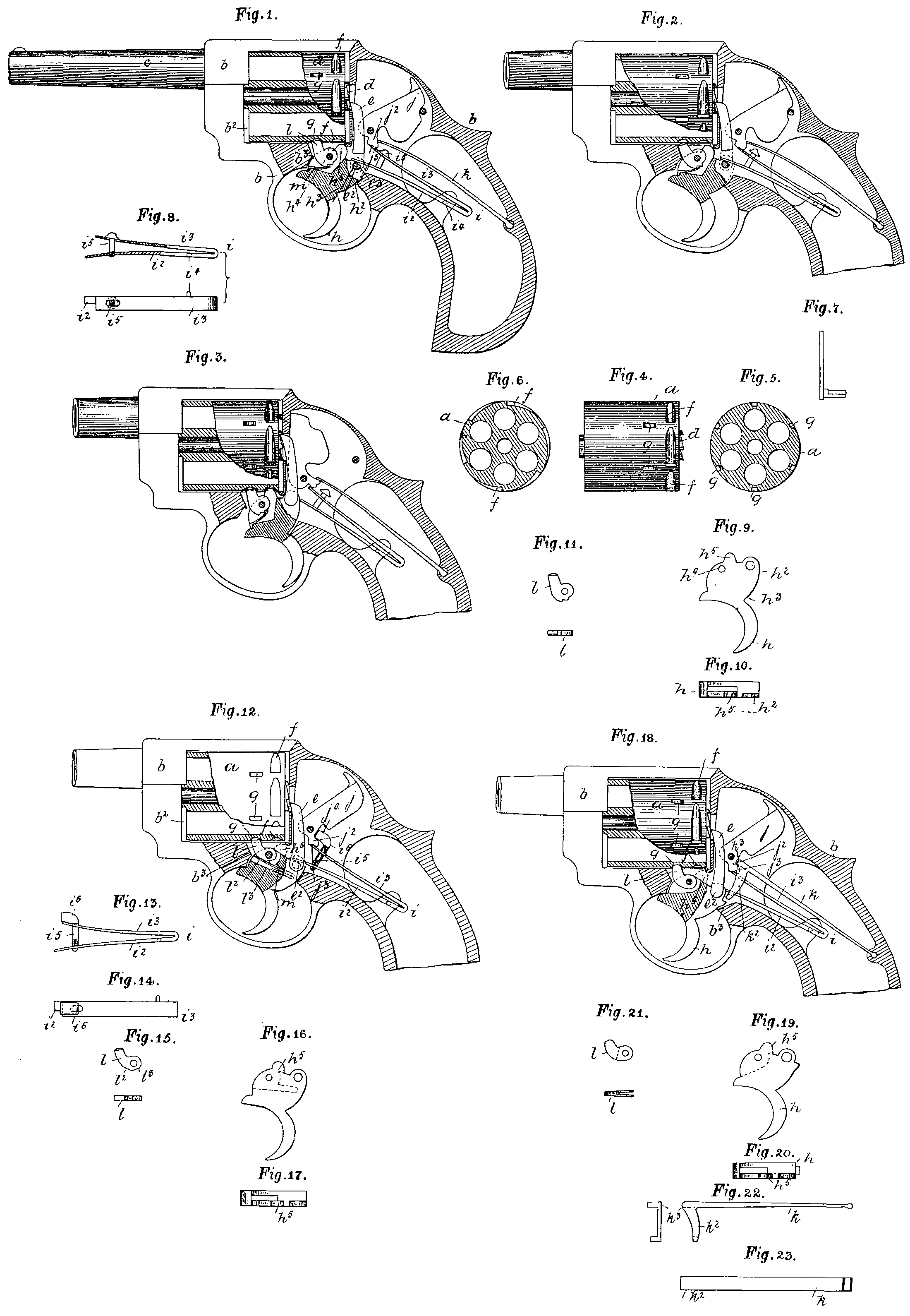
Figure 1 of the accompanying drawings, represents partly in vertical section, and partly in elevation, a solid frame revolver, constructed and arranged according to our invention.
It will be observed that the said arm is provided with a free cylinder, and is shown with the parts in the positions which they respectively assume, when it is ready for firing, by the pulling of the trigger.
Figure 2 represents a like view as figure 1, but with the trigger half-way pulled, and the second cylinder stop removed. or out of its holding position, while thus allows the free cylinder to rotate, for the bringing of a fresh and undischarged chamber before the nose of the hammer.
Figure 3 shows a like view as figures 1 and 2, but with the arm discharged, and the trigger fully pulled back into the position which it assumes on firing.
It will be observed, that both the cylinder stops are in their holding positions, whilst the top-side free-end of the main spring is holding the hammer forward, until the release of the trigger, by the removal from it of the finger of the user, when the hammer rebounds, and the cylinder is held only by the second stop.
Figure 4 represents in elevation the free cylinder, and figure 5 a transverse, section thereof, showing the second stop recesses, sunken at equal distances apart around the said cylinder. Figure 6 is a transverse section across the first stop recesses. Figure 7 is an edge view of the lifter, showing the faceted outstanding limb upon which the standside free end of the main spring takes its bearing. Figure 8 represents a side elevation, (partly in section) and plan of the main spring. Figure 9 is an elevation of the trigger, and figure 10 a top side plan thereof, showing the No. 1 locking arm and the rear of the blade, to which the lower end of the lifter is jointedly connected; so that by the pulling of the trigger back, the free cylinder is allowed to be rotated.
Figure 11 represents an elevation and plan of the second cylinder stop.
The same letters of reference indicate corresponding parts in figures 1 to 11.
a is a chambered and free working cylinder, working within a rectangular shaped recess b², of a solid frame b, whose fore part is provided with a barrel c, whose bore or axis is-coincident with the chambers within the said free cylinder, when the cylinder is rotated, so as to bring its chambers into position for firing. The chambered cylinder has a centrally disposed ratchet faced annulus d, at its rear, and with which the upper end of a lifter e, engages.
The said cylinder has double stop recesses f and g; the recess f we designate the first stop cylinder recess, and the recess g the second stop cylinder recess.
The lower end of the lifter e, has a flatted side e³ of a standing out limb e², which passes jointedly through a hole at the rear top side h² of the trigger blade h³, of the trigger h, while the free end lower side i², of the main spring i, takes its bearing upon the said flatted side of the lifter.
The upper limb i² of the main spring, nominally takes its bearing upon the under-side of the hammer j, of which the said underside is formed into an arm j², with full cock bent j³ made within it, and wherein the free end of the said limb i³ of the main spring i engages, when the hammer is fully cocked.
The approach to the bent resembles in form an: inclined plane; so that on forward pressure being applied to the same hammer as herein-after described, the said free end is removed.
It will be observed that the said main spring top side limb does duty both as a spring for throwing the hammer, and also as a sear for retaining it cocked.
The main spring rear part is swivelly connected at i⁴, to the solid frame, while its front and free ends are stayed by a headed pin i³. fixedly connected at its lower end to the lower limb i², and with its shank working through a hole made in the upper limb i³, and when the parts of the arm are in their normal positions, the underside of the head rests upon the top side of the upper limb, as represented at figure 1.
k is a supplementary spring, fixedly connected at one end to the framing, whilst its other end is free, and takes its bearing upon the inclined rear part of the arm j², of the hammer j; so that on the stay being elevated on the pulling of the trigger, the said free end is lifted or defected to the underside of the rear of the hammer, which being thereby pressed forward, takes the limb i², of the main spring out of bent, and so allows the hammer to fall, by the force exerted upon it of the said limb, acting below the centre, and upon the short arm j². It will be observed that the principle office of this said supplementary spring is for giving the rebound movement to the hammer after firing.
The trigger which consists of a trigger and trigger blade, and hung upon the centre h⁴, is provided with a fixed and also a movable cylinder stop.
h⁵ is the No. 1 cylinder stop, whilst l is the movable and No. 2 cylinder stop.
The functions of both stops is to hold the cylinder at two points, when the arm is discharged, and at one point on the return of the trigger.
The No. 2 stop consists of a jointed limb l, turning upon the same pin as the trigger, and the frame has an abutment b³, against which the No. 2 stop comes, and rests, on the first pulling of the trigger, and from which it again recedes (to the position as represented in figure 3) when the said trigger is fully pulled home.
The underside of the said stop has bents or notches cut or made within it, which form shoulders upon which the free end of the flat spring m, respectively takes, on the the trigger changing its position.
Thus the initial pull of the trigger carries the stop l with it, until its front side abuts and rests upon the stop b³, when the continued movement of the spring m, with the trigger, takes its free end from the neutral shoulder to the locking shoulder, which causes the stop to fly from the position figures 1 and 2, to that of figure 3.
The action of the mechanism of the arm is as follows:—
The initial pulling of the trigger, which is jointed upon the pin h⁴, turns the part h² rearwardly, and upwardly, thus raising the lifter e, and taking the locking arm h³, up to the entrance of one of the cylinder recesses f, and also at the same time takes l, the No. 2 cylinder stop out of onw of the cylinder recesses g, so as to leave the cylinder tree to move from right to left, which is done by the continued rising of the lifter, on the further pulling home of the trigger. For example, at the time when the lifter is elevated, which turns the cylinder round to the extent of a chamber, the No. 1 stop has passed into a No. 1 cylinder recess, and the No. 2 stop into a No. 2 cylinder recess, while the standside limb of the main spring, which rests upon the flat of the arm e² of the lifter e has been raised (top limb remaining quiescent) by the said arm, and with it the stay, whose bead is made to impinge upon the underside of the free end of the supplementary and rebound spring, thereby taking it from the incline at the rear of the arm of the tumbler, and pressing it against the underside of its haunched back, which gives a forward movement, to the hammer, and forces the end of the top limb of the main spring from out of the bent, which is done by an inclined plane or wedge action; thus, on the said end being free of the bent, the hammer falls, by the force of the said main spring.
The releasing of the trigger, causes the free end of the supplementary spring to press upon the inclined rear of the hammer, and so give its return movement, while the other parts of the mechanism resume their normal positions as represented in figure 1.
It will be understood that the second cylinder stop l is operated as follows.
That on the pulling of the trigger, the stop l is carried with it, until it comes in contact with the abutment b³, when its progress is arrested and held there, until the free end of the spring m has come upon the locking shoulder, when the said stop flies back into the position as in figure 3, and on the releasing of the trigger, the said spring’s free end comes upon the neutral shoulder as in figure 1, which holds it in this said position, until the trigger is again pulled.
Figure 12 represents a revolver with a free moving cylinder, constructed and arranged according to another form of our invention.
It will be seen in this arrangement or modification, that the supplementary or rebounding spring is dispensed with, and the bottom side limb of the main. spring made to fulfil its office, and also that the top side limb of main spring is used for the throwing of the hammer and keeping it cocked; that is to say, the said main spring has four duties to perform, viz.:— the rebounding of the hammer, the throwing of the hammer, keeping it in position when cocked, and also the keeping of the nose of the-lifter up to the teeth of the ratchet annulus; and further, it will also be seen that the second cylinder stop is provided with facets upon its underside, instead of points.
Figure 13 represents an elevation of the main spring and stay— Figure 14 a top side plan of the same— Figure 15 an elevation and plan of second cylinder stop, while figures 16 and 17 are elevation and plan of the trigger.
a is a free working chambered cylinder, turning upon a central axis, and moving within the rectangular recess b², of a solid frame b, whose stock, furniture and trigger guard are made in one piece with it.
The cylinder a has double stop recesses f, g, with which cylinder stops h⁵, l engage.
The stop h⁵ forms a part of the trigger h, whilst the stop l turns upon a pivot, and has neutral and locking facets l², l³, upon its underside, and upon which a flat spring m bears.
The rear top side of the trigger carries a jointed lifter e, which engages with a ratchet annulus at the rear of the cylinder a, and by means of which the said cylinder is partially rotated as aforesaid.
The main spring which is marked i, i², i³, has a threaded stay l⁵, whose shank lower end is attachedly connected to the lower limb i², whilst its upper end carries a head i⁵, which works within a gap j⁴ at the lower and rear side of the hammer j, above the arm j², whose underside has a bent or notch, wherein the extreme free end of the limb i² of the spring i engages, when the hammer is at cock, and upon the underside of which the said free end presses for throwing the hammer, for discharging the arm.
The stem of the stay works freely through a hole in the top limb; so that on the lower limb which rests upon the flat of a projecting arm e², of the lifter e, rising, the stay moves with it.
The action is as follows, when the mechanism of the arm is in the position as in figure 12.
The initial pulling or placing of the finger upon the trigger takes the stop l from one of the cylinder recesses g, raises the lifter e, and elevates the stop h⁵ to before one of the cylinder recesses f; so that the said cylinder is free to turn, which is done by the continued movement of the lifter to an extent equal to the bringing of a chamber into a top position before the hammer.
The raising of the arm e² has lifted or compressed the limb i² of the spring i, and elevated the stay i⁵, i⁶, and brought its head upon the top shoulder of the recess j⁴ of the hammer, whose initial pressure forces the end of the limb i³, from the bent j³ of the arm j², and allows the full force of the spring to be relieved, and exert itself upon the underside of the arm, and thereby throws the hammer which rebounds, on pressure being relieved from the trigger, and which rebound is effected by the underside of the head of the stay acting upon the top side of the arm, at the rear and foot of the hammer, or the bottom shoulder of the gap.
It will be observed that the second stop l acts exactly the same as the stop in figures 1, 2 and 3, other than the substition of facets for shoulders.
Figure 18 represents partly in vertical section, and partly in elevation, a revolver small-arm, constructed and arranged according to a modification or another form of this said invention.
The mechanism of this particular arrangement is comprehended in the main part by those of the former.
Figure 19 is an elevation of the trigger, while figure 20 is a plan of the same—
Figure 21 is the second cylinder stop, (plan and elevation) and figures 22 and 23 are separate views of an auxiliary rebound limb with a stay at its free end.
a is a free cylinder, turning upon a pivot axis, and working within a rectangular shaped opening in a solid frame b, whose rear body part is gapped, wherethrough the upper end of the lifter e works, and presses the cylinder round, by engaging with teeth of a ratchet annulus at the rear of the said cylinder.
The lower end of the lifter is jointedly connected to the trigger h, by a faceted arm e², upon which the standside free end i² of the main spring i, rests, whilst the upper side i³ takes within a bent j³, and presses upon the arm j², of the hammer j.
Connected with the main spring, is an auxiliary limb k, having at its free end a hooked stay k², which comes upon the underside of the free standside end i², of the main spring i, and is lifted by the rear top side of the trigger blade; so that on the pulling of the trigger, the lifter is raised, the chamber turned, the main spring compressed, and the auxiliary limb k lifted, which presses upon the top shoulder of the gap j⁴, and thereby gives a slight upward movement to the hammer, and relieves the end of the top side limb of the main spring from the bent, which now on the hammer being relieved, is urged forward by the stored up energy of the spring pressing itself against the underside of the arm j².
The releasing of the trigger allows the parts to resume their normal positions as in figure 18, and the extreme end or horn k³ to press upon the top and inclined side of the arm j², thereby making the said arm rebound.
The second cylinder stop which is marked l, is forked at its lower end, so as to embrace and bind within the joint part of the trigger wherein it works; so that on the trigger being pulled, the said second cylinder stop is taken out of the cylinder recess g, until it comes against the abutment b³ of the gap wherein it works, and thus allowing the trigger to be pulled home without it.
The trigger when relieved from pressure, reacts, and carries back with it the No. 2 cylinder stop, into one of the No. 2 recesses of the cylinder.
It will be observed that the said stop is carried to and fro only by its forked parts gripping the trigger; and further, the facet upon the lifter limb is for the purpose of keeping the nose of the said lifter up to the teeth of the ratchet annulus, for driving the cylinder, The first cylinder recess and stop are marked respectively f, h⁵.
Having now particularly described and ascertained the nature of our said invention, and in what manner the same is to be performed, we declare that what we claim is:—
First:— Locking or holding a free-moving chambered cylinder of a repeater small arm, by a stop h⁵ made with the trigger or trigger blade, and a pivoted stop l, carried by it, and which operate and co-operate substantially as and for the purpose as set forth.
Secondly:— In a second cylinder stop, making the trigger carry the spring, by means of which the said stop is governed, as set forth.
Thirdly:— Making the top side free end of the main spring act in common for both sear and main spring, as set forth.
Fourthly:— Providing the main spring with a stay, fixed to the lower limb, and acting upon the free end of a supplementary spring, for the purpose as set forth.
Fifthly:— Constructing the hammers of repeater small arms with an arm j², with bent on underside, wherein the free end of a main spring engages, and upon which said arm it presses, as set forth.
Sixthly:— The rebounding of the hammer into full bent, by the return of the trigger.
Seventhly:— The combination with the main spring and its stay i², i³, i⁴, i⁵ of a supplementary spring k, whose free end acts upon an incline at the rear of the foot of the hammer, whereby the said hammer is made to rebound, on finger pressure being relieved from the trigger.
Eighthly:— Constructing and arranging the parts of repeater small-arms as herein described and set forth in figures 1, 2 and 4 of the drawings.
Ninthly:— A main spring and stay, constructed and working substantially as herein described and set forth in figures 12, 13, and 14, whereby the top side limb of the spring is made to fulfil the office of main spring and sear, whilst the lower limb, through the intervention of the stay is made to act as a rebound spring.
Tenth:— The combination with a main spring, or a main spring and stay, swivelly connected and working as set forth in figure 12, of a hammer, with an arm notched (bent) on its underside and a gap j⁴ substantially as set forth.
Eleventhly:— A revolver small arm, consisting of the parts which are constructed, arranged and operates substantially as and for the purpose as set forth in figure 12.
Twelfihly:— Creating the rebound of the hammer, by an auxiliary limb, with stay k, ², k³, as set forth.
Thirteenthly:— In a second cylinder stop, splitting or sub-dividing the lower end of the stop into spring or yielding sides, which bind within or upon the trigger blade, which operate and work substantially as and for the purpose as set forth.
Lastly:— A repeater small-arm, the construction, arrangement and combination of the parts as herein described and set forth in figure 18.
Dated this Sixteenth day of January 1889.
JOHN CARTER.
WILLIAM JOHN WHITING.
By Henry Skerrett,
Agent for Applicants.