
Britain 9973
A.D. 1885, 22nd August. Nº 9973.
PROVISIONAL SPECIFICATION.
Improvements in Revolving Small Arms.
I Haralamb Dimmancea of Bucharest, Roumania, but now residing at № 299 Aston Lane, Witton near Birmingham in the County of Warwick, Captain in the Roumanian Artillery, do hereby declare the nature of the said invention for “Improvements in revolving small arms” to be as follows:—
My invention consists of the construction and arrangements of the parts of revolving small arms herein after described, whereby great simplicity in the construction of the said small arms and efficiency in their action are secured.
I will describe my invention in connection with a revolving pistol.
On the underside of the rear end of the long fixed or non-revolving barrel, is a block or bracket carrying the pin or axis on which the short revolving cylinder, containing the charge chambers, turns. Below the hole or bearing in which the said pin or.axis is fixed, is another hole or bearing parallel thereto. In this last named hole or bearing a pin or axis forming a prolongation of the lower part of the body of the pistol engages. Upon this pin or axis the block or bracket carrying,
the fixed barrel and the revolving cylinder turns, so that by turning the said bracket through a quadrant, either to the right or left, the rear end of the revolving cylinder is exposed. The cases of the exploded cartridges can now be extracted and the cylinder recharged.
The discharging or extracting of the cases of the exploded cartridges is effected by sliding the bracket on the axis on which it turns. The extractor, which is engaged with the rims of the cartridges, is fixed to the body of the pistol and retains the cases of the cartridges while the revolving cylinder by the sliding motion referred to, slides from off the said cases which are thereby extracted. When the bracket, after charging the cylinder, is restored to its normal position, the frame in which the-revolving cylinder works may be locked to the body of the pistol by a bolt, This bolt on being withdrawn effects the withdrawal of the striker sufficiently far to permit of the revolving cylinder being turned aside without obstruction.
The intermittent rotary motion of the cylinder, the cocking of the striker and the discharge of the pistol are effected by mechanism constructed as follows— In the body of the pistol is a double wheel consisting of two series of equi-distant and nearly similar radial arms, equal in number to the number of charge chambers in the revolving cylinder the said two series of arms being parallel and turning together. The arms of one part of the double wheel are somewhat shorter than those of the other part and I will distinguish them as long arms and short arms. The double wheel is mounted upon an axis crossing the body of the pistol and on the same level as the axis on which the revolving chamber turns. The said wheel can only rotate in one direction.
The intermittent rotary motion of the cylinder is effected on pressure of the trigger by one of the long arms acting upon a ratchet wheel at the base of the cylinder, Having turned the cylinder through the required angle, the arm escapes from the ratchet wheel and the upper end of the raised trigger takes into one of a series of notches on the edge of, the cylinder and fixes-it in position during discharge The upper arm of the trigger is so jointed that while in its advance motion it acts on the arm of the wheel, on its return motion the said upper arm turns upon the joint and passes under the arm of the wheel without moving it.
The striker, which has a sliding motion in the line of the axis of the fixed barrel and is urged forward by a coiled or other spring, is forced back on pressing the trigger by the action of that long arm of the wheel which for the time being is vertical, This long arm bearing against a shoulder on the striker forces the striker back and compresses the main spring, The striker is temporarily fixed in position or cocked by one, of the short arms engaging with the top of a short lever turning independently on the same axis as the trigger The discharge of the pistol is
effected by further pressure on the rigger. This further pressure causes the long arm which cocked the striker to press it beyond its cocked position. The short arm which held the striker cocked is now disengaged from the short lever described, find the long arm escaping from the shoulder of the striker, the latter is urged forward by the compressed: main spring and the pistol is discharged. By repeated pressures on the trigger the actions described may be repeated until all the chambers are discharged when the pistol: may be recharged by unbolting the frame carrying the revolving cylinder, turning it-aside and withdrawing. the cases of the spent cartridges as already described.
The application of my improvements to revolving guns differs in no essential respect from its application to pistols as hereinbefore described.
Dated this 22d day of August 1885.
W. T. WHITEMAN,
Agent for the Applicant.
COMPLETE SPECIFICATION.
Improvements in Revolving Small Arms.
I Haralamb Dimmancea of Bucharest, Roumania, but now residing at № 299 Aston Lane, Witton near Birmingham in the, County of Warwick, Captain in the Roumanian Artillery, do hereby declare the nature of this Invention and in what manner the same is to be performed to be particularly described and ascertained in and by the following statement:—
My invention consists of the construction and arrangements of the parts of revolving small arms herein after described, whereby g great simplicity in the construction of the said small arms and efficiency i in their action are secured.
I will describe my invention in connection with a revolving pistol.
On the underside of the rear nd of the long fixed or non-revolving barrel is a block or bracket carrying the pin or axis on which the short revolving cylinder containing the charge chambers turns. Below the hole or bearing in which the said pin or axis is fixed is another hole or bearing parallel thereto. In this last named hole or bearing a pin or axis forming a prolongation of the lower part of the body of the pistol engages. Upon this pin or axis the block or bracket carrying the fixed barrel and the revolving cylinder turns, so that by turning the said bracket, through a quadrant the rear end of the revolving cylinder is exposed. The cases of the exploded cartridges can now be extracted and the cylinder recharged.
The discharging or extracting of the cases of the exploded cartridges is effected by sliding the bracket on the axis on which it turns. ‘The extractor which is engaged with the rims of the cartridges is fixed to the body of the pistol and retains the cases of the cartridges, while the revolving cylinder by the sliding | motion referred to slides from off the said cases which are thereby extracted. When the bracket after charging the cylinder is restored to its normal position he frame in which the revolving cylinder works may be locked to the body of the pistol by a bolt. This bolt on being withdrawn effects the withdrawal of the striker sufficiently far to permit of the revolving cylinder being turned aside without obstruction.
The intermittent rotary motion of the cylinder the cocking of the striker and the discharge of the pistol are effected by mechanism constructed as follows:— In the body of the pistol is a double wheel consisting of two series of equidistant and nearly similar radial arms equal in number to the number of charge chambers in the revolving cylinder the said two series of arms being parallel and turning together. The arms of one part of the double wheel are somewhat shorter than those of the other part and I will distinguish them as long arms and short arms. The double wheel is mounted upon an axis crossing the body of the pistol and on the same level as the axis on which the revolving chamber turns. The said wheel can only rotate in one direction.
The intermittent rotary motion of the cylinder is effected on pressure of the trigger by one of the long arms acting upon a ratchet wheel at the base of the cylinder. Having turned the cylinder through the required angle the arm escapes from the ratchet wheel. The upper arm of the trigger is so jointed that while in its advance motion it acts on the arm of the wheel on its return motion the said upper arm turns upon the joint and passes under the arm of the wheel without moving it.
The striker which has a sliding motion in the line of the axis of the fixed barrel and is urged forward by a coiled or other spring is forced back on pressing the trigger by the action of that short arm of the wheel which for the time being is vertical. This short arm bearing against a shoulder on the striker forces the striker back and compresses the main spring, The discharge of the pistol is effected by further pressure on the trigger, This further pressure causes the short arm which cocked the striker to press it beyond its cocked position. The short arm which held the striker cocked escaping from the shoulder of the striker the latter is urged forward by the compressed main spring and the pistol is discharged.
I will now proceed to describe with reference to the accompanying Drawings the manner in which my invention is to be performed.
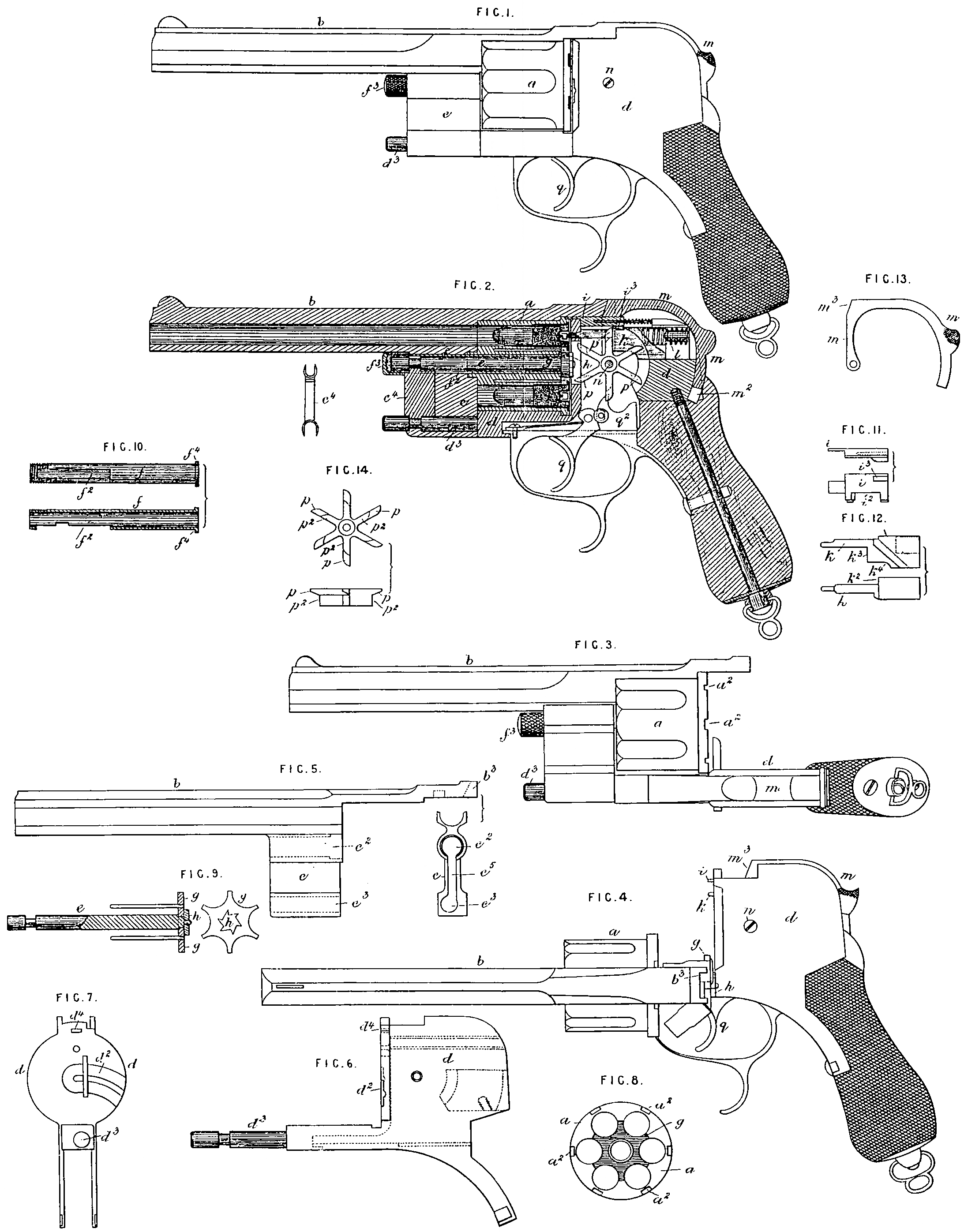
Figure 1 represents in side elevation and Figure 2 in longitudinal vertical section, a revolving pistol containing my improvements; Figure 3 represents the pistol in side elevation with-the rear ends of the charge chambers of the revolving cylinder open or exposed for loading or inspection and Figure 4 represents the same in plan after the revolving cylinder has been drawn forward for extracting the empty cartridge cases; Figure 5 represents in side elevation the fixed barrel and its block or bracket detached from the pistol, the said Figure 5 also exhibiting an end elevation of the said bracket; Figure 6 represents in side elevation and Figure 7 in end elevation the body or shoe of the pistol detached; Figure 8 represents an elevation of the rear end of the revolving cylinder; Figure 9 represents in side elevation, partly in section and end elevation, the extractor detached, together with the pin or axis of the revolving cylinder, The other Figures represent details of the pistol as herein after described. The same letters of reference indicate the same parts in the several Figures of the Drawings.
a is the revolving cylinder of the pistol and b the long fixed barrel on the underside of which is a bracket on block c having in it two longitudinal and parallel holes c², c³ between which is a vertical slot c⁵ (see Figure 5); d is the shoe or body of the pistol; e is the fixed pin or axis on which the revolving cylinder a turns the said pin or axis e being situated and working in the bearing or hole c² in the bracket c, The said cylinder a is not supported directly on the pin or axis e but is carried by the fixed tubular sleeve f surrounding the said axis. The said sleeve f is fixed to the bracket c by the screw cap f screwed on the end of the said sleeve, The said tubular sleeve f is shown detached in plan and longitudinal section in Figure 10. The said sleeve f is furnished with a longitudinal slot f² for permitting of the sliding of the bracket c in extracting the cartridge cases. The rear end of the sleeve has a collar f⁴ which engages with the revolving cylinder a (see Figure 1) On the end of the pin or axis e the extractor g is fixed, the said extractor g taking into a recess in the rear face of the revolving cylinder q as usual, guide pins on the extractor engaging in holes in the said cylinder a so that the cylinder a and extractor g rotate together. The rear end of the pin or axis e carrying the extractor g takes a bearing in a quadrant slot in the face of the body or shoe d and the rear end of the said pin or axis has secured to it the ratchet wheel h, It is through the ratchet wheel h operated in the manner herein after described that the intermittent rotary motion is given to the revolving cylinder a. In the face of the body or shoe d a quadrant slot and depression d² (see Figure 7) is made for receiving the reduced end of the pin or axis e and the ratchet wheel h, The said slot and depression at d² permits the revolving cylinder a carried by the bracket c of the fixed barrel, being turned aside for exposing the rear ends of the charge chambers in the said cylinder a for charging them and for extracting the empty cartridge cases.
The turning aside of the said revolving cylinder is effected in the following manner. On the body or shoe d is a pin or axis d³ forming a prolongation of the lower part of the said body of the pistol (see Figure 6). The pin or axis d³ engages in the second and lower hole or bearing c³ in the bracket c on the fixed barrel b. Upon the lower, pin or axis d³, the block or bracket c carrying the fixed barrel b rotates so that by turning the said bracket (by grasping the fixed barrel a) through a quadrant, the rear end of the revolving cylinder is removed from the face of the fixed body or shoe d and the rear ends of the charge chambers in the said cylinder thereby exposed as illustrated in Figure 3 and when in this position the cases of the exploded cartridges can be extracted and the cylinder recharged, As the revolving cylinder is turned aside the end of the axis e and the ratchet wheel h move in the quadrant slot and depression d² in the face of the fixed body or shoe d. The two parallel rods or axes e and d³ are coupled together by the connecting piece c⁴ (see Figure 2) having forks or loops at the top and bottom which are engaged with the annular depressions or necks in the ends of the said rods, thereby permitting of the rotation of the said rods in the forks but preventing the sliding of the said rods. The vertical slot c⁵ in the bracket c and the slot f² in the fixed sleeve f work over the fixed coupling piece c⁴ in extracting the empty cartridge cases.
In order to extract the empty cartridge cases when the rear ends of the charge chambers of the revolving cylinder a are exposed as represented in Figure 3, the bracket c, by means of the barrel b carrying it, is pulled forward so as to slide the said bracket c on the axis or pin d³ on which it turns, the revolving cylinder a sliding with the said bracket. By this sliding motion of the revolving cylinder a it elides from off the cartridge cases which are retained by the non-sliding extractor g and the said cases are thereby extracted from the chambers of the revolving cylinder as illustrated in Figure 4; 4 is the spring sliding bolt (shown separately in Figure 11) for locking the revolving cylinder a in its place after each intermittent motion. The said bolt works through the hole d⁴ in the face of the body d and in succession takes into the recesses a², a² in the rear end of the cylinder a (see Figure 8). The barrel b is locked to the body d by the lever bolt m, shown separately in Figure 13, turning on the cross pin or axis n, the free end of the said lever bolt working in a curved recess m² in the rear end of the body or shoe d. The lever bolt m is pressed into its acting position by the striker k which is urged forward to discharge the pistol by the strong main spring l. The front end m³ of the lever bolt m when pressed forward takes into a recess b³ in the strap of the fixed barrel b and thereby fastens the body to the barrel. The striker k is represented separately in Figure 12. The spring bolt i is withdrawn to permit of the revolving cylinder a being turned aside by means of the lever bolt m the said lever bolt m also at the same time slightly withdrawing the striker k to bring its nose flush with the face of the body d. The front end of the hand lever m engages with the recess i² in the side of the bolt i and also bears against the shoulder k on the striker k so that when the free end of the lever bolt m is pressed down into its slot m² in the body or shoe d, the forward end of the said lever bolt simultaneously withdraws the bolt i and striker k and the body d is unfastened from the fixed barrel b and the revolving cylinder a can be turned aside as herein before described.
The spring bolt i and striker k are guided in their motions by feathers on their sides working in longitudinal grooves in the cheeks of the body d.
p, p² is the double wheel turning on the same centre as that on which the lever bolt m turns, The double wheel p, p² is shown separately in Figure 14. By means of this double wheel the intermittent rotary motion is given to the revolving cylinder a the bolt i and striker k withdrawn to permit of the motion of the said cylinder, the striker k cocked and released and the pistol discharged. The said double wheel consists of two series of equi-distant and nearly similar. radial arms, the arms of one series being longer than those of the other series. The long arms are marked p and the short arms are marked p² (see the separate view, of, the wheel Figure 14). The long arms p of the double wheel operate upon the ratchet wheel h and withdraw the bolt i and the short arms p² withdraw and cock the striker k. The long arms p work through a vertical slot in the face of the body d to reach the ratchet wheel h. The said wheel is driven or advanced by the trigger acting upon the short arms p² of the said wheel and the back motion of the wheel is prevented by one of the short arms p² bearing against the underside at k⁴ of the striker k, The trigger is marked q and has jointed to it a loose upper arm or pawl q² which operates the arms p² of the wheel. When the trigger q is pulled the advance and rise of its upper jointed arm or pawl q² acts on one of the short arms p² of the wheel, which arm q² of the trigger in its return motion passes under the next arm p² of the wheel without moving it.
On the advance of the double wheel p, p² by the action of the trigger, the bolt i is withdrawn by the extreme end of the long arm p which for the time being is vertical acting against the rib i² on the underside of the bolt i (see Figure 11). By the same motion of the double wheel, the short arm p² slightly withdraws the striker k by acting against the shoulder k² on the said striker. As soon as the bolt i and striker k have been withdrawn to unfasten the revolving cylinder a, another of the long arms p of the wheel p, p² acting upon the ratchet wheel h moves the revolving cylinder through the required angle. This further advance motion of the double wheel causes the arm p² which is bearing upon the striker k to force it back and compress the main spring l. The continued advance of the double wheel causes the long arm p first to escape from the rib i³ on the bolt i (which advances and locks the revolving cylinder a) and the short arm p² afterwards to escape from the cocked striker which is now disengaged and being urged forward by the main spring l discharges the pistol. By repeated pressures on the trigger q the actions described may be repeated until all the chambers of the revolving cylinder a are discharged, when the pistol may be recharged by unbolting the frame or shoe d from the part carrying the revolving cylinder, turning the said cylinder aside and withdrawing the cases of the spent cartridges as herein before described and illustrated.
The application of my improvements to revolving guns differs in no essential respect from its application to pistols as herein before described and illustrated.
Having now particularly described and ascertained the nature of my invention and the manner in which the same is to be performed I declare that I claim as my invention of “Improvements in revolving small arm”
First— The construction and combination of parts substantially as herein before described and illustrated in the accompanying Drawings, whereby the revolving cylinder can be turned aside for exposing the rear ends of the charge chambers of the said cylinder for reloading or inspection.
Secondly— The construction and combination of parts substantially as herein before described and illustrated in the accompanying Drawings for extracting the spent cartridge cases from the chambers of the revolving cylinder by the sliding motion of the barrel, revolving cylinder and -parts carried by them from the body , or shoo of the pistol or small arm.
Thirdly— Fixing the body or shoe to the barrel and locking the revolving cylinder in its place during discharge by means of the spring lever bolt m and spring sliding bolt i and withdrawing the said sliding bolt and the striker by means of the lever bolt m substantially as herein before described and illustrated in the accompanying Drawings.
Fourthly— Discharging the cartridges in the charge chambers of the revolving cylinder by means of the spring sliding striker k, l the said striker being arranged and operating substantially as herein before described and illustrated in the accompanying Drawings.
Lastly— Giving the intermittent rotary motion to the revolving cylinder, withdrawing and releasing the locking bolt and cocking and releasing the striker by means of the double wheel p, p² used in conjunction with and operated by the loose upper arm trigger. q, q² substantially as herein before described and illustrated in the accompanying Drawings.
Dated this fourteenth day of May 1886.
W. T. WHITEMAN,
Agent for the Applicant.