
British 2497
LETTERS PATENT to Charles Hanson, of Pimlico, in the County of Middlesex, Gunsmith, for the Invention of “ Improvements in Fire-arms.” Sealed the 1st April 1856, and dated the 7th November 1855.
PROVISIONAL SPECIFICATION left by the said Charles Hanson at the Office of the Commissioners of Patents, with his Petition, on the 7th November 1855.
I, Charles Hanson, of Pimlico, in the County of Middlesex, Gunsmith, do hereby declare the nature of the said Invention for “ Improvements in Fire-arms ” to be as follows:—
My improvements relate to revolving pistols and other small arms, parts of which can be applied to arms in which the breech is stationary, and consist in simplifying the parts known as the 44 action ” of the fire-arm.
For revolving arms I compose my action of six parts; trigger, hammer, rotator, mainspring, spring lever for holding the hammer at half or full cock prior to the arm being discharged by pulling the trigger, and detent for the purpose of locking all the parts of the44 action ” when required, as, for instance, in loading, or for insuring safety in carrying the arm. The trigger is composed of a bolt, which slides in a slot in the under part of the lock plate, and from about the centre depends the bow, by which the trigger is set in motion ; the back end of the bolt terminates in a swan neck, which is notched to receive the end of an arm projecting from the front and bottom part of the hammer; the rotator or lever, whereby the breech is caused to rotate, is pinned on to the side of the swan neck end of the bolt. The hammer consists of an upright shaft, terminate? at top in a thumb piece of the usual shape, and cap discharger, and at bottom in a circular piece, which rides upon the inside of the bottom of the lock plate;! near the bottom it is centered upon a pin, and is perforated to allow of the insertion of this pin. The fore part of the shaft near the bottom is formed into a circular-shaped projecting arm, terminating at bottom in an edge, whid takes into the V notch in the end of the trigger holt; at front this arm is notched to receive the edge of the cocking spring lever, and between this pro-1 jeering arm and the aperture made for the centering pin, the hammer is hollowed out, to allow of the swan neck falling therein to set free the hammer and discharge the piece. Another arm projects forward from the bottom o( the hammer, and receives thereon a projection from the inside of the swan neck, which enables the lock to be “ cocked ” either by the hammer or theli trigger. The back of the hammer is formed at its lower part with a camshaped piece, between the bottom of which and the lower part of the lock plate the ends of the mainspring are inserted. The spring lever for holding fiw hammer rests upon the outside of the further side of the lock plate; this spring lever terminates in an arm which projects inwards, and which is pressed 3 against and into the notches on the fore part of the projecting notched arm of the hammer, before, described. After the lock has been! placed at tuft cock, the arm on the spring lever k liberated, from the nptch on the projecting arm of the hammer by a projection on the inner side of the swan, nock, ip. which the trigger bolt terminate^ and, allows the hammer tp be pressed forward by ^ ‘ mainspring, and the fire-arm to bp thereby discharged. The locking detent is fixed on the outside of the lock plate, and on the side opposite to that on which the cocking spring leyeij is plaped. This detent can bp paoved by the hand into a, notch in the fore part of the rotator, whereby tbe whole action will be effectually locked.
For carbines, fpwHng pieces, and other spa all arms of similar description, apd whether with stationary pr revolving breech, I prolong the back end of the trigger bplt, and make it to tpripin^te in a projecting plate behind the ordinary trigger guard, which allows of the lock being cocked,, by grasping the arm and projecting plate while raising it to the shoulder, whereby the plate and trigger holt will be pulled up and the hammer placed at full cock. With stationary breech arms I dispense with the rotator.
SPECIFICATION in pursuance of the conditions of the Letters Patent, filed by the said Charles Hanson in the Great Seal Patent Office on the 7th May 1856.
TO ALL TO WHOM THESE PRESENTS SHALL COME, I, Charles Hanson, of Pimlico, in the County of Middlesex, Gunsmith, send greeting.
WHEREAS Her most Excellent Majesty Queen Victoria, by Her Letters Patent, bearing date the Seventh day of November, in the year of our Lord One thousand eight hundred and fifty-five, in the nineteenth year of Her reign, did, for Herself, Her heirs and successors, give and grant unto me, the said Charles Hanson, Her special licence that I, the said Charles Hanson, my executors, administrators, and assigns, or such others as I, the said Charles Hanson, my executors, administrators, and assigns, should at any time agree with, and no others, from time to time and at all times thereafter during the term therein expressed, should and lawfully might make, use, exercise, and vend, within the United Kingdom of Great Britain and Ireland, the Channel Islands, and Isle of Man, an Invention for “ Improvements in Fire-arms,” upon the condition (amongst others) that I, the said Charles Hanson, my executors or administrators, by an instrument in writing under my, or their, or one of their hands and seals, should particularly describe and ascertain the nature of the said Invention, and in what manner the same was to be performed, and cause the same to be filed in the Great Seal Patent Office within six calendar months next and immediately after the date of the said Letters Patent.
NOW KNOW YE, that I, the said Charles Hanson, do hereby declare the nature of my said Invention, and in what manner the same is to be performed, to be particularly described and ascertained in and by the following statement thereof, reference being had to the Drawings hereunto annexed, that is to say:—
My improvements relate to revolving pistols and other small arms, parts of them being applicable to arms in which the breech is stationary, and consist in simplifying the part known as the “ action ” of the fire-arm.
For revolving arms I compose my “ action ” of six parts; trigger, hammer, rotator, mainspring, spring lever for holding the hammer at half or full cock prior to the arm being discharged by pulling the trigger, and a detent for the purpose of locking all the parts of the “ action ” when required, as, for instance, in loading, or for insuring safety in carrying the arm. The trigger is composed of a bolt, which moves in a slot in the under part of the lock plate, and from about the centre depends the bow, by which the trigger is set in motion, The back end of the bolt terminates in a swan neck, which is notched to receive the end of an arm projecting from the front and bottom part of the hammer. The rotator or lever by which the breech is caused to rotate is pinned on to the side of the swan-neck end of the bolt. The hammer consists> of an upright shaft, terminating at top in a thumb piece of the usual shape, and a cap discharger, and at bottom in a circular piece, which rides upon the inside of the bottom of the lock plate; near the bottom it is centered upon» pin, and is perforated to allow of the insertion of this pin. The fore part of the shaft near the bottom is formed into a circular-shaped projecting arm, ter*^ minating at bottom in an edge, which takes into the V notch in the end of the trigger bolt; at front this arm is notched to receive the edge of the cocking spring lever, and between this projecting arm and the aperture made for the centering pin the hammer is hollowed out, to allow of the swan neck falling therein to set free the hammer and discharge the piece. Another arm project^ forward from the bottom of the hammer, and receives thereon a projection from the inside of the swan neck, which enables the lock to be cocked either by the hammer or the trigger. The back of the hammer is formed at its lower part with a cam-shaped piece, between the bottom of which and the lower part of the lock plate the ends of the mainspring are inserted. The spring levei^ for holding the hammer rests upon the outside of the further side of the loci plate. This spring lever terminates in an arm which projects inwards, and which is pressed against and into the notches on the fore part of the projecting notched arm of the hammer, before described. After the lock has been placed at full cock, the arm on the spring lever is liberated from the notch on* the projecting arm of the hammer by a projection on the inner side of the swan neck, in which the trigger bolt terminates, and allows the hammer to be pressed forward by the mainspring, and the fire-arm to be thereby discharged The locking detent is fixed on the outside of the lock plate, and on the side opposite to that on which the cocking spring lever is placed. This detent can be moved by the hand into a notch in the fore part of the rotator, whereby the whole action will be effectually locked.
For carbines, fowling pieces, and other small arms of similar description, and whether with stationary or revolving breeches, I prolong the back end of the trigger bolt, and make it to terminate in a projecting plate behind the ‘ ordinary trigger guard. The locking detent before mentioned is in this case dispensed with. In stationary breech arms I also dispense with the rotator.
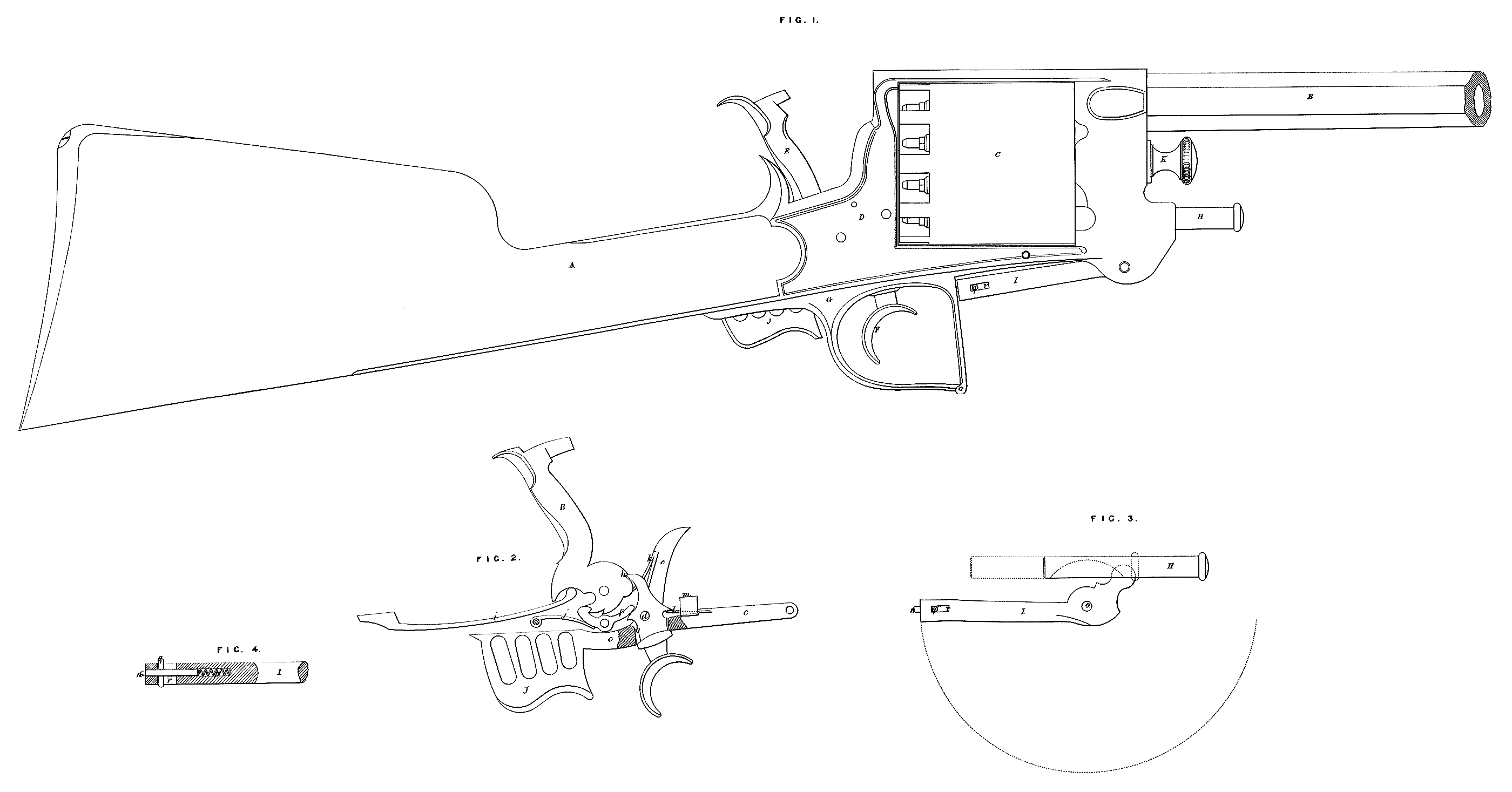
In the Drawings hereunto annexed I have represented a gun to which the principle of my improved action is applied, and in which the parts are substantially the same as those before described.
Figure 1 is a side elevation of the gun. A is the stock; B, the barrel; C, the revolving cylinder, containing the charge chambers; D, the lock casing; E, the cock; F, the trigger; G, the trigger guard; H, the ramrod; I, the ramrod lever; J, a projecting portion of the lever on which the trigger is . carried; and K, the head of a bolt on which the cylinder C revolves, and the end of which screws into the hinder portion of the lock case, and imparts strength to the combination of parts.
Figure 2 is a detached view of the lock, shewn on cock, to the parts of which the same letters are applied as in Figure 1. The trigger F is passed through a slot b in the lever c, and is held there by a pin d, which is formed on one side of the rotator e, and passes through the trigger; and the trigger lever / is a small lever, one end of which bears against the trigger F when at full cock, while the other is formed with a hooked end, which takes into a notch on the lower part of the cock, as shewn. The second notch, shewn on that part of the cock, is for the hooked end of the small lever / to take into when the gun is half cocked. The lever c, which has the projecting portion J, before mentioned, formed upon it, is centered at its full extremity on a pin, which passes through it at g. The upper extremity of the trigger F catches in a notch h in the cock. i,j, k, l, are springs, which act upon the cock E, the lever/, the rotator e, and the trigger F respectively.
The principal object of the foregoing arrangement is to prevent the gun from being discharged when the trigger alone is pulled (as it often is by accident), and to render it necessary to both move the trigger and raise the lever c by pressing the projection J upwards, in order to discharge it. The parts are therefore so formed and arranged, that when the trigger only is pulled the lever drops, and the cock is retained in its position by the hooked end of the lever/; but when the lever c is raised, the lever / is thereby forced upwards, and the cock thus released, m is a projection on the lever c, which projection takes into the back end of the revolving cylinder to lock the latter while the gun is discharged. The rotation of the barrel is effected by the rotator ef which acts against ratchet teeth in the end of the revolving cylinder, when the lever c is raised as heretofore in ordinary revolvers.
Figure 3 is a detached view of the ramrod and its lever. The lever I is centered on a pin at o, and the end of its short arm takes into a slot in the ramrod H, which latter slides into and out of the charge chambers as the lever is moved away from and back towards the stock of the musket. The lines which the ends of the lever I and the end of to ramrod trace in their motion are indicated in dotted lines in Figure 3. The leVer I is secured when not in use in the position shewn in Figure 1, by means of a pin which takes into a hole in the trigger guard G. This pin n slides in a hole bored lengthways in the end of the lever I, being pressed out by a spring pf shewn in the sectional view, Figure 4. When the ramrod is to be used, the pin n is withdrawn from the hole in the trigger guard by means of a transverse pin q, formed upon the pin ?i, this transverse pin projecting through a slot r in the side of the lever I.
And having now described the nature of my said Invention, and in What manner the same is to be performed* I declare that I claim,—*
First, the construction of an “action” for fire-arms as herein-before described, and represented in the Drawings hereunto annexed.
Second, the method of connecting the trigger with a lever which lias a motion about a centre in such manner, that in order to discharge the fire-arm the lever must be raised and the trigger pulled simultaneously, as herein-before described, and represented in the Drawings hereunto annexed.
Third, to method of working the ramrod of revolving fire-arms by means of a bent lever centered on a pin, and with its end taking into a slot in to ramrod, as herein-before described, and represented in to Drawings hereunto annexed.
In witness whereof, I, the said Charles Hanson, have hereunto set iny hand and seal, this Seventh day of May, One thousand eight hundred and fifty-six.
C. HANSON. (L.S.)