
British 2018
LETTERS PATENT to Charles Pryse, of Birmingham, in the County of Warwick, Gun Manufacturer, and Paul Cashmore, of West Bromwich, in the County of Stafford, Pistol Manufacturer, for the Invention of “ Certain Improvements in Repeating Fire-arms.”
Sealed the 15th February 1856, and dated the 6th September 1855.
PROVISIONAL SPECIFICATION left by the said Charles Pryse and Paul Cashmore at the Office of the Commissioners of Patents, with their Petition, on the 6th September 1855.
We, Charles Pryse, of Birmingham, in the County of Warwick, Gun Manufacturer, and Paul Cashmore, of West Bromwich, in the County of Stafford, Pistol Manufacturer, do hereby declare the nature of the said Invention for “ Certain Improvements in Repeating Fire-arms ” to be as follows:—
Our improvements consist, firstly, in constructing repeating fire-arms that shall have a double action, by which the hammer may be put on either half cock or full eock, and which is accomplished in the following manner, that is to say, by employing a cock, as shewn at (E, Figure 1), or by attaching a lifting piece to the back of the hammer. The hammer is formed on a tumbler (T), on the under side of which there are two notches, into which a small tooth °a the sear (S) clicks or catches in cooking, the one being for half and the other for full cock. The trigger (G) is formed in two parts, one working within the other, as shewn by the dotted lines, and by this arrangement it works both the lever (L) and the sear (S). (B, Figure 1,) is a bolt, securing the cock and revolving chambers at one and the same time.
Secondly, our improvements relate to the ramrods used for these arms, and in the mode of holding them to the barrel when not in use; this will be readily understood on reference to the Drawings, in which two forms of spring fastenings are shewn at (Z).
Thirdly, our improvements relate to single-action repeating fire-arms, simplifying their construction, and increasing their durability by using a trigger of the form shewn at (T), (Figure 3). On cocking the pistol, the stop (S) acts upon the revolving chambers, securing them until after the pistol has been fired, when on releasing the trigger the stop also releases the chambers. The bolt, which is not seen in the Drawing, but is on the outside of the body, locks both cock and chambers for safety, one arm of it catching into a bolt plate (P) secured to the tumbler, and the other arm into a notch on the revolving chambers. We also make the body of the arm (X) out of a solid piece of metal, if found preferable.
SPECIFICATION in pursuance of the conditions of the Letters Patent, filed by the said Charles Pryse and Paul Cashmore in the Great Seal Patent Office on the 4th March 1856.
TO ALL TO WHOM THESE PBESENTS SHALL COME, we, Charles Pryse, of Birmingham, in the County of Warwick, Gun Manufacturer, and Paul Cashmore, of West Bromwich, in the County of Stafford, Pistol Manufacturer, send greeting.
WHEBEAS Her most Excellent Majesty Queen Victoria, by Her Letters Patent, bearing date the Sixth day of September, in the year of our Lord One thousand eight hundred and fifty-five, in the nineteenth year of Her reign, did, for Herself, Her heirs and successors, give and grant unto us, the said Charles Pryse and Paul Cashmore, Her special licence that we, the said Charles Pryse and Paul Cashmore, our executors, administrators, and assigns, or such others as we, the said Charles Pryse and Paul Cashmore, our executors, administrators, and assigns, should at any time agree with, and no others, from time to time and at all times thereafter during the term therein expressed, should and lawfully might make, use, exercise, and vend, within the United Kingdom of Great Britain and Ireland, the Channel Islands, and Isle of Man, an Invention for “ Certain Improvements in Repeating Fire-aems,” upon the condition (amongst others) that we, the said Charles Pryse and Paul Cashmore, by an instrument in writing under our hands and seals, should particularly describe and ascertain the nature of the said Invention, and in what manner the same was to be performed, and cause the same to be filed in the Great Seal Patent Office within six calendar months next and immediately after the date of the said Letters Patent,
HOW KNOW YE, that we, the said Charles Pryse and Paul Cashmore, do hereby declare the nature of our said Invention, and in what manner the same is to be performed, to be particularly described and ascertained in and by the following statement, reference being had to the Drawings hereunto annexed, and to the letters and figures marked thereon (that is to say):—
Our Invention consists, firstly, of an improved construction of repeating firearm, having a double action, and self-acting or non-self-acting, that is to say, that may be cocked either by means of the trigger or by the use of a thumb piece on the hammer, neither of these actions interfering with the utility of the weapon or its rapidity of fire as a repeating arm, and in making the body or frame of this arm in one piece of metal.
Secondly, our improvements consist in certain modifications of the above, which we term single-action repeating arms, as they must be cocked by means of the thumb piece, consequently are not self-acting; the body of these arms we also make of one piece, if preferred.
Thirdly, our Invention consists in improved means of applying lever ramrods, for the purpose of ramming the charge in those repeating arms which consist of a cylinder or series of chambers revolving in a line parallel to the line of a stationary barrel, through which barrel all the chambers of the breech cylinder are discharged.
Fourthly, our Invention consists of improvements in the spring catches, employed for the purpose of securing the ramrod close to the barrel when not in use.
And, lastly, in improved forms of double-acting bolt, which will prevent the chambers from revolving, and secure the hammer or striker at half cock at the same time.
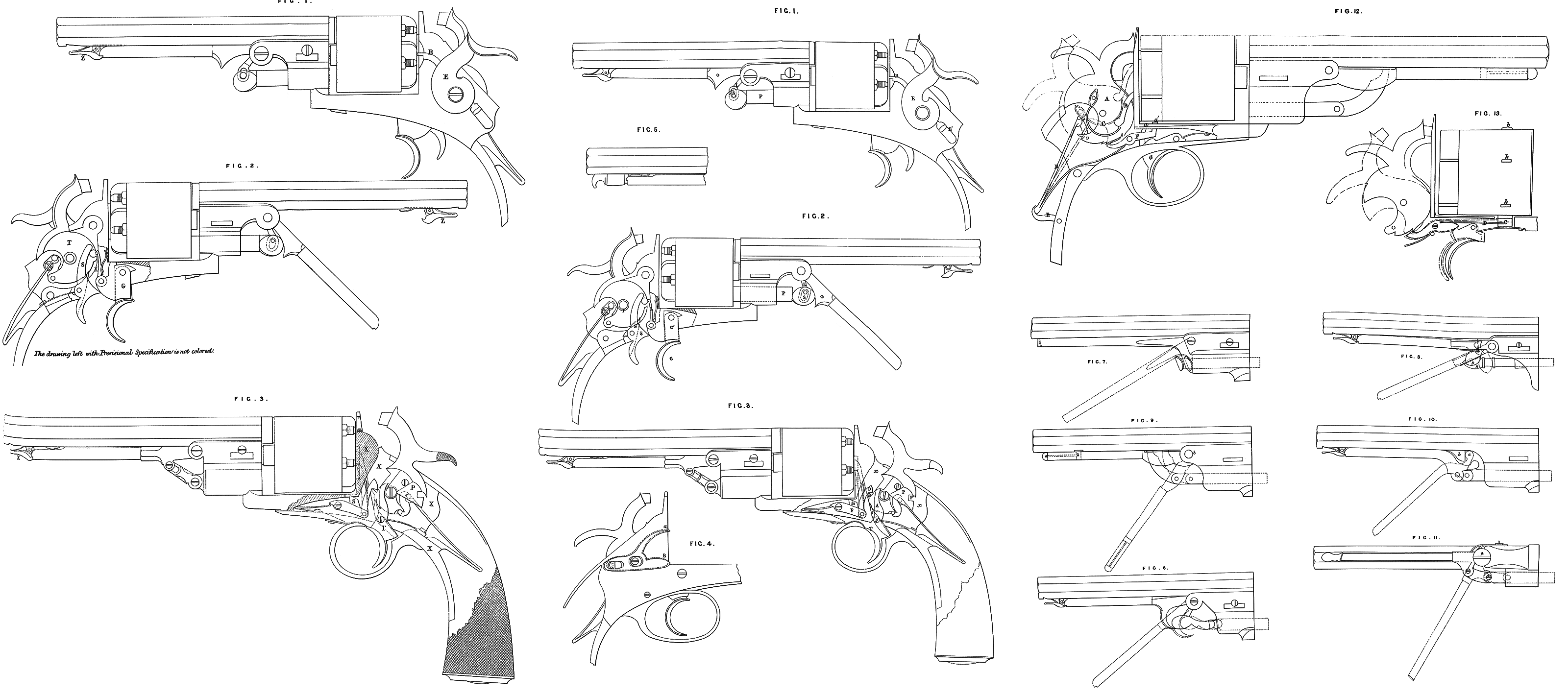
Description of the Drawings.
Sheet A: Figure 1 is an elevation of one of the double-action pistols, before named, with the stock removed. Sheet A : Figure 2 is an elevation of the opposite side of the same pistol, with the body removed, and shewing the details of the lock; Figure 3 shews one of the single-action pistols; Figure 4, one of the forms of double-acting bolt, above alluded to; Figure 5, one of our improved ramrod clicks or fastenings.
Sheet B: Figures. 12 and 13 represent other arrangements of the lock and stop of single-action pistols.
Sheet C shews various views of our improvements in applying lever ramrods, some of which, with their improved catches, are also shewn in the Drawings before enumerated.
We now proceed to describe the action of the lock, shewn in (Figure 2), which is that of the self-acting double-action pistol. (G) is the trigger, formed in two parts; a plate secured to the finger bow is held in a jaw (G1) that forms the body of the trigger, and has a slight play in its bearings, as indicated by the dotted lines. (S) is a sear, having a second sear (S1) on the under side, seen also in dotted lines, which takes into bents on notches on the under side of the tumbler (T); this double sear may be formed in one piece, if preferred. (L) is an arm or lever, pinned loosely to the body of the trigger, and furnished at its upper end with a small stud, catching in a bent on thp front of the tumbler. By the action of this lever, on drawing back the trigger the hammer is raised, the sear (S1) clicks into the upper notch or bent on the under side of the tumbler when the hammer is put on half cock, and into the lower notch when it is put on full cock, which must be done by drawing back the thumb piece on the hammer; a very slight pull on the bow of the trigger will be sufficient to cause the striker to fall and fire the pistol. By employing the trigger only without touching the thumb piece, the pistol becomes selfacting, and may be used as an ordinary repeater. (Figure 3) shews one of our improved single-action repeating pistols, that is to say, it can only be cocked by the use of the thumb piece on the hammer, and cannot, as in that shewn in (Figure 2,) be half cocked by drawing the trigger. The sear (S) is in this case placed behind the trigger (T), and clicks into bents or notches on the under side of the tumbler, in the same manner as that shewn in Figure 2; the action of drawing back the trigger releases the sear, and allows the striker to fall. On cocking the pistol, the stop (S1) is brought up against a flange on the chambers to hold the chambers in a fixed position until the arm has been discharged; this is effected by the tumbler raising the lever (F) on which the stop is fixed, by means of the jaw (D), hanging upon a projecting stud (E) in front of the tumbler. We desire to maintain this stop in position and to keep the chambers fast until the trigger has been released from the pressure of the finger, for which purpose the upper part of the trigger is formed into a long arm (A), which arm, on the striker falling, drops under the jaw (D), and suspends it until the trigger is released, when the stop (S1) drops, and the chambers are Again free to revolve. (X, X,) Figure (3,) shews that part of the pistol which we term the body, and which we make entire from one solid piece of metal. •Ehe details of the lock shewn in Sheet B, (Figure 12,) the action of whose parts is indicated by the red lines, also belong to the class of repeating arm which we have designated single-acting, (A) is the tumbler; (B), the driver; (C), the driver spring; (D), the main Spring, kept in its place by a moveable dog or catch (E), instead of being fixed by a pin or rivet; (F) is the sear; and (G), the trigger. This lock can easily be taken to pieces and refitted by the most unskilled operator. The stop for fixing the rotation of the breech .cylinder is in this case formed by the combined action of the trigger and the sear, on each of which is a short arm (a, a1,) passing through a slot in the frame under the chamber, and between these two arms on the trigger and sear one of the flanges of the cylinder is held, except when the arm is at half cock, at which point the cylinder will revolve freely. (Figure 13) shews another .form of stop, for securing the chambers, and which consists of small studs (6) forged on to the cylinder, and a butt or slotted stud (C) on the end of an arm ;(D), which projects from the sear; the action of half cocking depresses this -butt (C), and allows of the revolution of the chambers; but at full cock, and also when the hammer is down, one of the studs (£) is held between the teeth of the biltt (G), and the revolution of the cylinder is thereby prevented. A reverse action, or a stud upon the sear taking into a slot upon the cyliuder, would also answer the purpose as well, but need not be further described.
The next part,of our Invention relates to improvements in applying lever ramrods for ramming the charges in the breech cylinders or chambers, various forms of which are shewn in the Drawings; that shewn in (Figures 1 and 2) is .simply a plunger;(P), pinned to the fulcrum of the lever by a link (L), through which is a slot (S), working on a pin on the head of the plunger. The part (Q) of the lever which comes into contact with the plunger is shaped to a form the better to suit the head of the plunger and to give greater purchase. In (Figure 3) the lever is pinned to the plunger by a chain link placed at some distance from the fulcrum. (Figure 6) shews one on the same principle as that seen in Figures 1 and 2, but somewhat extended; and (Figure 7) represents a simpler form, in which the head of the plunger is flattened, and furnished with a small butt, under which the lever embraces the top of the .plunger, the object of this arrangement being, that should the plunger after ramming :adhere to the ball, as is frequently the case, the return of the lever to its position of rest releases the plunger. (Figure 8) shews a form of rammer adapted for loading the chambers more at the side than immediately under the barrel, and consists of a block (B), secured to the side of the -lever at the fulcrum, between the jaws of which block the head (H) of the plunger is held, the shape of this block piece being such as to maintain the motion of the plunger in a line parallel with the barrel. (Figure 9) shews a form of rammer that may be made either with or without a fixed fulcrum, being kept in its proper direction by a quadrant-shaped guide piece, formed on the head of the plunger, and passing through a slot in the lever. On the descent of the lever the quadrant guide works freely down the under side of the barrel, a fulcrum being obtained by forming the lower end of the lever so as to hook or catch under any suitable projection on the bracket piece, as at (B), or, if preferred, it may be pinned at that point. Figure 10 gives another form of lever rammer, working without being fixed to the fulcrum by the butt (a) on the heel of the lever, catching under the projecting stud (B) on the barrel, as seen in the dotted lines ; and (Figure 11) shews a rammer adapted to work at the side of the barrel instead of underneath, and in a* plane at right angles to those already described, the lever being connected to the plunger by a single link, and the fulcrum formed by shaping the end of the lever into a ring, which works round a stud on the barrel, and is prevented from slipping by a large headed screw passing through the end of the lever, as at (a), and taking into the before-named stud upon the barrel.
In reference to our improvements in the clicks or spring catches for holding the lever of the rammer up to the under side of the barrel when not in use, one form is seen at (Figure 5, Sheet A), consisting of a plug (a), passed through a collar (J), and furnished with a thumb piece at the end. A spiral spring round, or a flat one under, the plug keeps it in position, so that when the lever is brought up to the barrel the end clicks into a notch in the plug. It is released by drawing back the plug by means of the thumb piece at the end, a flat spring on the barrel throwing out the lever when the plug is pulled out. In the form of catch seen in the rest of the Drawings (with the exception of that seen at Figure 7, which is not new’,) and Figure 9, a flat thumb piece works on a pin passing through a stud on the barrel; a flat spring is fixed under the thumb piece, which spring may be made either in one piece with the catch, or in a separate piece pinned to the barrel or the catch, and on pressing the thumb piece down at the end nearest the muzzle of the barrel, a spring on the barrel under the end of the lever throws the lever out; on returning the lever it is retained by the beak of the catch engaging in a notch on the end of the lever. The catch shewn in (Figure 9) consists of a spring let into the side of the lever, and connected to a small thin strip of metal, secured by a pin passed through the centre of its length, on which it works. One end is provided with a thumb piece (a), and the* opposite end with a small stud, that passes into a slot in the centre of the lever, and into which a notched catch (6) on the barrel engages when the lever is brought up to the barrel, the stud of the spring taking into the notch in the catch (S) until it is required for use, when a slight pressure on the thumb piece (a) releases it. The catch seen in (Figure 11) is the same as one already described, but varied in the form of the beak to suit the lever, which, as before stated, works in a plane at right angles to that of all the others.
The last part of our Invention, namely, the bolt for securing the chambers and the hammer at half cock at one and the same time, is shewn in (Figures 1 and 3), a portion of its action being seen in each Figure, and in a modified form at (Figure 4). B, B1, (Figure 1,) is a thin piece of metal, passing under the cocking piece (E), (which in the Drawing is a separate piece at the side, but a thumb piece on the hammer will answer equally, as in Figure 4,) behind which one arm of the bolt passes through a slot in the body of the pistol, and is provided with a small stud formed to engage in the notch (P1) of the bolt plate (P), Figure 3, which bolt plate is fixed on the tumbler. The bolt has a thumb catch at the end (Bl), for the purpose of sliding it forward and backward, and the extended arm (B) has on its extreme end a stud that catches in notches on the chambers; thus, by sliding forwards the bolt (B, B\ Figure 1), both the chambers and the hammer will be locked at the same time. (Figure 4) shews a modification of this bolt, the upper arm (a) of which secures the chambers, and the lower one (£) the hammer. This form of bolt is applicable to either description of pistol.
We would explain, that although we have mentioned pistols throughout in this our Specification, we have done so only for the sake of brevity, as these our improvements are intended to be applied to repeating arms of any other description than pistols; but as the details of all the important parts would be the same, further description is unnecessary.
Having thus described the nature of our said Invention, and in what manner the same is to be performed, we wish it to be clearly understood that that which we claim is,—
Firstly, the mode of obtaining a double action in repeating fire-arms, by the employment of the trigger and sear, described and shewn in Drawings, by which we can put the arm at half cock by using either of the two movements, namely, by the thumb piece or by the trigger, whilst it is also a self-acting repeating arm, if desired ; and also making the body of the arm, whether single or double-acting, from a solid piece of metal.
Secondly, the mode of constructing single-action repeating arms, by the employment of a trigger and sear, as shewn in the Drawings, and by which also, in conjunction with the stop described, We can prevent the revolution of the chambers until the trigger is relieved from the pressure of the finger; and we also claim the general arrangement and combination of the parts of the lock seen in Figures (12 and 13), with the inodes of stopping the rotation of the chambers therein shewn, and described in this our Specification.
Thirdly, we claim the various modes we have shewn and described of applying lever rammers.
Fourthly, the forms of click or spring catch seen in the Drawings (with the exception of that in Figure 7), for the purpose of retaining the lever in its due position under the barrel when not in use.
Fifthly, the forms of double-acting bolt, for securing the chambers and fixing the hammer at half cock simultaneously.
In witness whereof, we, the said Charles Pryse and Paul Cashmore, have hereunto set our hands and seals, this Third day of March, in the year of our Lord One thousand eight hundred and fifty-six.
CHARLES (l.s.) PRYSE. PAUL (l.8.) CASHMORE.
.Witness,
Edward John Payne.