
British 1359
LETTERS PATENT to Joseph Enouy, residing at No. 31, Denbigh Place, Pimlico, in the Parish of St George’s, Hanover Square, Middlesex, for the Invention of “ The Means of 4 Removal * of every Rotary or Revolving 4 Barrel or Cylinder ’ containing Chambers from all Revolver Pistols, Guns, and Fire-arms, and the 4 Substitution ’ in their Place by another and other 4 Barrels or Cylinders * in succession.”
Sealed the 11th December 1855, and dated the 14th June 1855.
PROVISIONAL SPECIFICATION left by the said Joseph Enouy at the Office of the Commissioners of Patents, with his Petition, on the 14th June 1855.
I, Joseph Enouy, of No. 31, Denbigh Place, Pimlico, do hereby declare the nature of the said Invention for ‘‘The Means op ‘Removal* of eveby Rotaby ob Revolving ‘Babbel ob Cylindeb’ containing Chambebs fbom all Revolveb Pistols, Guns, and Fibe-abms, and the ‘Substitution* in theib Place by anotheb and otheb ‘ Babbels ob Cylindebs ’ in succession,” to be as follows:—
Any given number of barrels or cylinders containing chambers revolving singly upon their own axis, from number one upwards, and conjointly or seperately move either in connection or rotate upon a common axis, may be so arranged as to be used successively until the whole given number in such fire-arm are brought towards the lock for the purpose of being discharged. These barrels or cylinders are secured to a framework, on or in which they move, and rotate by the action of the lock. Say number one of any given number of barrels or cylinders that may be in the framework is against the lock for being discharged: after it is discharged, or at any time for the purpose of removal, a rod is withdrawn, a forward action is applied to the framework, which removes the cylinder from the lock, and a movement or rotation of such framework brings forward another cylinder, say, number two; the framework is then returned, which brings the cylinder close to the lock; the rod is then replaced, and this cylinder rotates and discharges by the action of the lock of said fire-arm. The same process is repeated throughout the whole number of barrels or cylinders that may be affixed to the framework, or that may be in connection with each other, both in the withdrawing and replacing of each and every cylinder in said fire-arm. The framework is fixed to the stock of said fire-arm at one part, and by an upright fastening at another part connects it with the long tube through which the discharge passes. A bar or bars attached to the upper or lateral part of the long tube connects it with the stock of sd fire-arm. The necessary quantity and form of pins, bolts, plates, screws, nuts, and fastenings that may be used in constructing this apparatus for fire-arm to be specially included in complete Specification.
SPECIFICATION in pursuance of the conditions of the Letters Patent, filed by the said Joseph Enouy in the Great Seal Patent Office on the 14th December 1855.
TO ALL TO WHOM THESE PRESENTS SHALL COME, I, Joseph Enouy, residing at No. 31, Denbigh Place, Pimlico, in the Parish of St. George s, Hanover Square, Middlesex, send greeting.
WHEREAS Her most Excellent Majesty Queen Victoria, by Her Letters Patent, bearing date the Fourteenth day of June, in the year of our Lord One thousand eight hundred and fifty-five, in the eighteenth year of Her reign, did, for Herself, Her heirs and successors, give and grant unto me, the said Joseph Enouy, Her special licence that I, the said Joseph Enouy, my executors, administrators, and assigns, or such others as I, the said Joseph Enouy, my executors, administrators, and assigns, should at any time agree with, and no others, from time to time and at all times thereafter during the term therein expressed, should and lawfully might make, use, exercise, and vend, within the United Kingdom of Great Britain and Ireland, the Channel Islands, and Isle of Man, an Invention for “ The Means op * Removal * op every Rotary or Revolving ‘ Barrel or Cylinder ’ containing Chambers from all Revolver Pistols, G-uns, and Fire-arm3, and the 4 Substitution * in their Place by another and other ‘ Barrels or Cylinders ’ in succession,” upon the condition (amongst others) that I, the said Joseph Enouy, by an instrument in writing under my hand and seal, should particularly describe and ascertain the nature of the said Invention, and in what maimer the same was to be performed, and cause the same to be filed in the Great Seal Patent Office within six calendar months next and immediately after the date of the said Letters Patent.
NOW KNOW YE, that I, the said Joseph Enouy, do hereby declare the nature of the said Invention, and in what manner the same is to be performed, to be particularly described and ascertained in and by the following statement, reference being had to the Drawings hereunto annexed in the accompanying Plate:—
It is the custom with the manufacturers of repeating guns and pistols to procure, if required, an additional revolving barrel or cylinder, so that each fire-arm may be provided with a set of two, the one already fitted to and forming part of the gun or pistol; the other is loose, and has to be applied in the place of the first one after its entire discharge.
I have thought it possible in this my Invention, that instead of this second loose barrel, which is not only awkward to carry but frequently forgotten, to unite the two revolving barrels or cylinders containing chambers together by means of a framework, on and within which they may rotate, and, by other arrangements and appliances, that as soon as the first barrel had discharged its contents, then, by a little mechanical contrivance, this one should be removed, and immediately the second barrel should replace the first, both always remaining fixed to the fire-arm.
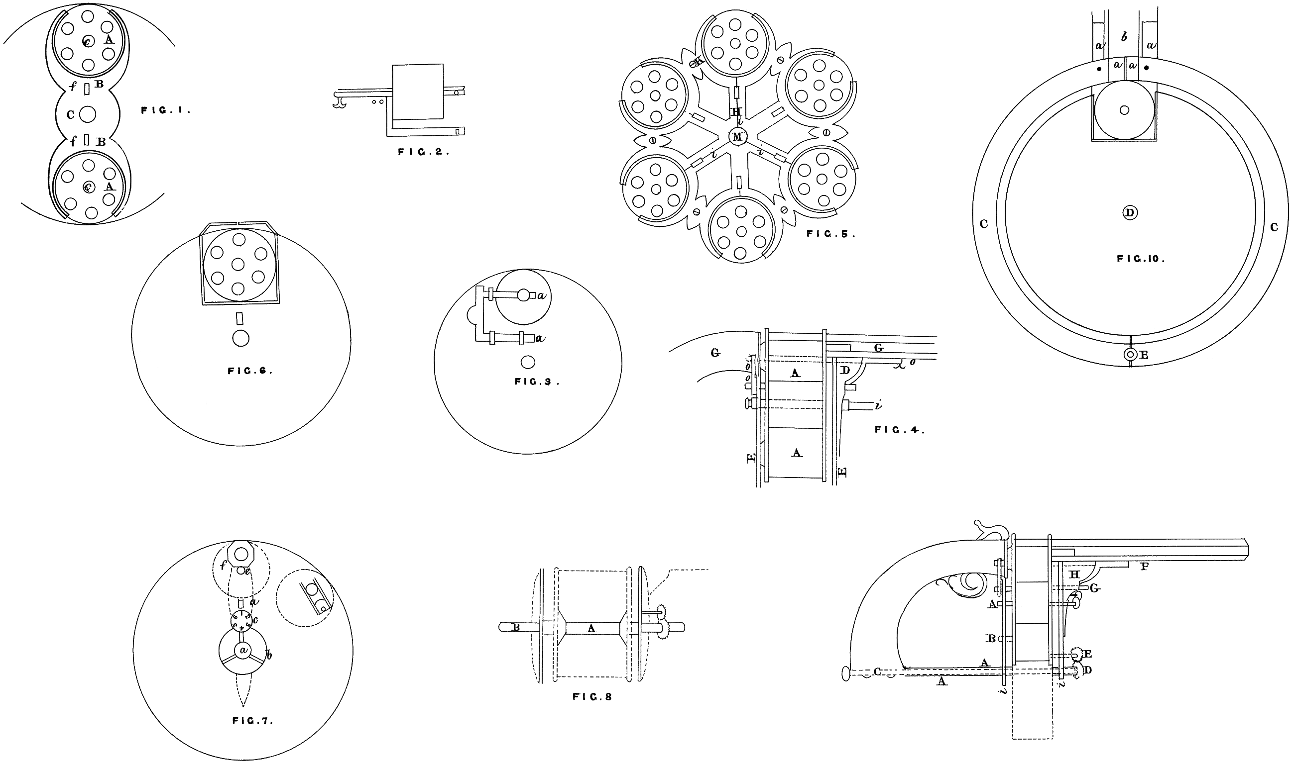
Figure 1 shews an end elevation of the two barrels A, A, fitted into a framework B, B, with an opening in the centre C, through which a rod or axle runs, and on which the framework moves and revolves perfectly free, c, c, in the centres of each barrel are openings for the rods, and the two vertical openings/,/, are for the lock bolt to pass through, united to the rod at the other end, and have at their extremities eyelet holes or apertures to receive a cross key bolt at angles, which secures the framework at one end in connection with the long tube through which the discharge passes, and at the other end to the framework of the lock or stock of fire-arm.
Figure 2 shews a side elevation of a revolving barrel with rod and lock bolt united o, o, with the apertures at their extremities to receive the key bolt; these pass through the entire framework. Portion of the upper part of the rod has a projecting ledge, fitted to a grooved channel, in which it slides in the securing and releasing of the framework.
Figure 3 shews an end elevation of a revolving barrel A with part of framework attached; the ends of both rod and lock bolt are secured by the key bolt acting in a transverse direction a, a, outside a plate, as in Figure 6.
Figure 4 is a side elevation of two barrels A, A, fitted to framework with bracket D. Under the tube and against the outside plate, as shewn in Figure 7, the rod o is passed through the barrel into the centre opening of the lock, and the lock bolt o, 0, passed through the entire framework, the rod o resting on and through two plates E, E, G, G, portions of the tube and lock part of fire-arm; the central rod is an axle for the work to rotate upon i.
Figure 5 is an end elevation of one of the two moulded frame plates H, with perforations I to lessen the weight. On and within it are fitted six revolving barrels or cylinders with chambers; six are here represented capable of receiving thirty-six rounds of cartridge at once. Grooves are turned on the extreme ends and edges of each barrel, which are fitted to and rest upon a moulding of frame plate, to enable them freely to rotate, and confine them in their proper place. K are screws uniting the two frame “plates** together, the “ outside ** one next the tube, and the “ rear ’* one next the lock; the three lines z, z, i, meeting in the centre are portions of the framework; into each are let a revolving barrel, in case the remaining barrels are dispensed with, and a framework with three of them being preferred to six. By this triangular arrangement one barrel is always to the lock, and the two others are placed one on each side of it, so balancing the weight of fire-arm. The central opening in the barrel and the long square aperture in the framework under the barrel shews where the rod and lock bolt enter; the framework and barrels together rotate upon a rod passed through the central orifice M.
Figure 6 is a view of outside rear plate fitted to the framework and lock part of fire-arm, shewing an opening at the top, and one of the revolving barrels close to the lock; the two angles uniting on the top and over the barrel are bars, one on each side of the tube, fastened to it and to framework of the lock; it covers the upper part of framework, and unites the tube and stock of fire-arm together.
Figure 7 is the outside forward plate, being the fellow to the one in Fig. 6, and fitted to the tube bar or bars and bracket of framework. The central orifice a is for a rod to pass through; a ratchet or other wheel b turns round over this rod, and acts upon a disk wheel c, with the number of revolving barrels on its face in figures, shewing the exact number that have been discharged from the entire number that may be attached to the framework. d, the long square opening above the disk plate with the small aperture above. e shews where the lock bolt and rod passes into and through the framework. The large opening on the top of plate/is where the long tube (through which the discharge passes) is united to the plate. The circular hole in the centre of this opening is one of the chambers of a revolving barrel, which is against the tube. Lower down and near the edge of the plate is a circular opening, through which are passed the cartridges into every chamber of each revolving barrel as they are successively brought towards it for the purpose of re-loading. This aperture may be close to the tube, by which the appliance of a ramrod in connection may be useful. This opening is covered by a spring door, which slides within a frame; the dotted lines running down on either side of apertures and projections, and terminating at a part below the centre of plate, shews the place where the bracket rests underneath and with the tube and against the plate. Around each of these fellow plates, Fig. 6 and 7, and at their edges are strips of plate* let on and projecting inwards at angles with the plates, covering a portion of framework round and outside the top of it.
Figure 8 is a side elevation outline of framework, with a tube A passed through the centre, containing a rod B within, on which the tube and framework united runs, with block ends pinned to the framework; this serves as a stay* and maintains the diameter in the centre between both frameworks, equal to the diameter at its circumference; the outline of bracket, ratchet, or other wheel, the disk wheel, and both outside plates are shewn at either sides.
Figure 9 is a side elevation of framework as fitted to a small fire-arm. This Figure is.to shew that, according to the number of revolving barrels that may be constructed within and to this apparatus, so the radius of each is extended and the circumference may be enlarged. A represents the axis or centre of framework, constructed with two revolving barrels; B with three or six barrels, and C with nine barrels. In this case the radius is extended to the stock, and the axle fastened to it, allowing room for the hand to hold the fire-arm. D is the ratchet wheel, attached to the tube A, A, and framework, and extended up to the stock and over the axle rod C, and when moved, by the finger and thumb being applied to the projecting divisions on its surface (or other appliance), partially rotates the entire framework, while a motion of the disk wheel E is also obtained, indicating the number of each partial rotations. F, rod; G, lock bolt; H, bracket; i, i, outside plates.
Figure 10 are two half-circular plates, united at the top and to the bar or bars by springs, and extending round and over the entire upper and lower outside of framework, and united at the bottom by a swivel fastening. These plates have each a lap extending down the two outsides, and fitted on and over the two outside plates, both forward and rear one. These two half-circular top plates, with the two outside end plates correctly fitted into their several adjoining parts with their fastenings form a case, over and within which case the body of framework of this apparatus is connected to and included, and protected from danger of any kind, a, a, two bars connecting the tube with
stock; b9 tube; C, C, two half-plates (circular), with lap edges turned down; the two dots are springs; the square opening shews a revolving barrel against the lock of fire-arm. D, centre axis; and E, swivel, fastening the two plates together. This apparatus, which is a multiplying revolver, may be fitted to all repeating or revolving fire-arms.
I claim this as my Invention, 1st, the arrangement of any given number of revolving barrels or cylinders containing chambers from number one upwards, unlimited, affixed to or within and on a framework, which by a movement or partial rotation brings each and every barrel successively towards the lock of a fire-arm, whether each barrel moves separately in its own frame and on a seperate axis, or in combination with the others upon one general axle, in this great “ compound magazine,** being a “ series ** of “ magazines *’ in connection and arrangement within a framework.
2nd, I claim the form and structure of each seperate and every part in and of this mechanical apparatus, as may be applicable to the combined and general character of this Invention, as heretofore described.
3rd, I claim the combination and arrangement of each and every part for the general purposes herein intended.
4th, I claim the entire structure, including each and every part, both seperate and combined in their arrangement, and for the singular and general purposes intended, to the effect and according to the title of this my Invention.
In witness whereof, I, the said Joseph Enouy, have hereunto set my hand and seal, this Fourteenth day of December, in the year of our Lord One thousand eight hundred and fifty-five.
JOSEPH ENOUY. (l.s.)