
US 505569
UNITED STATES PATENT OFFICE.
CHARLES W. HOPKINS AND JAMES BOLAND, OF NORWICH, CONNECTICUT.
SAFETY-CATCH FOR FIREARMS.
SPECIFICATION forming part of Letters Patent No. 505,569, dated September 26, 1893.
Application filed March 27, 1893, Serial No. 467,737, (No model.)
To all whom it may concern:
Be it known that we, Charles W. Hopkins and James Boland, citizens of the United whereas in our improved form such impact is States, residing at Norwich, in the county of New London and State of Connecticut, have invented certain new and useful Improvements in Firearms, which improvements are fully set forth and described in the following specification, reference being had to the accompanying sheet of drawings.
Our invention relates to that class of arms in which the hammer is concealed, and is here illustrated as applied to a revolver.
The objects of said invention are, first, to provide a breech-frame in which certain parts of the lock (particularly the firing-pin and hammer) may be more conveniently assembled and adjusted than in “solid frame” arms, and which, when finished, shall have no openings through which dirt or moisture can enter and, second, to provide a simple safety device by means of which the hammer may be locked in its closed or inoperative position to guard against accidental discharge.
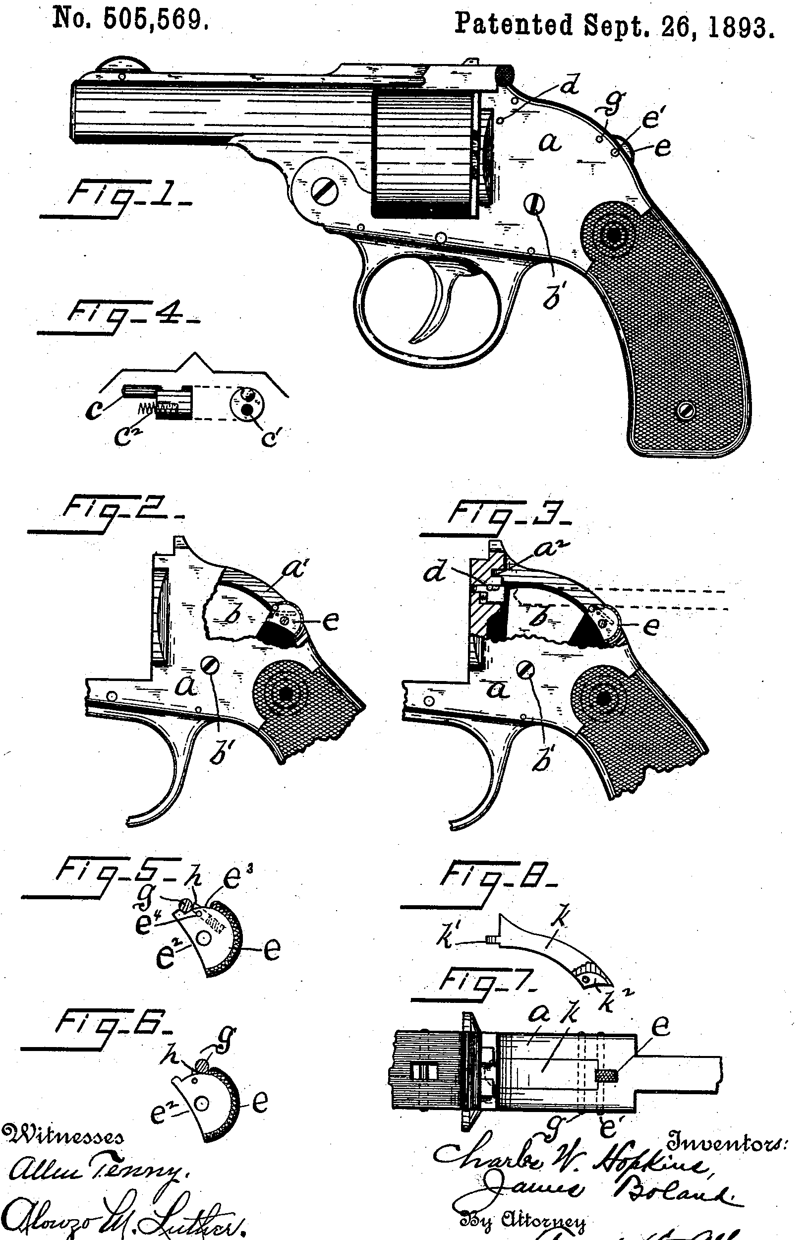
In the annexed drawings, Figure 1 is a side view of a revolver of our improved form. Figs. 2 and 3 are similar views of that portion of the breech frame that contains the lock-work; said frame being broken away, in part. Fig. 4 shows side, and front end, views of the firing-pin detached and enlarged. Figs. 5 and 6 are detached, side, views of our “safety disk” or thumb-piece, used in connection with the hammer. Fig. 7 is a top view of the major portion of the breech frame and Fig. 8 is a side view of a plate used to close the otherwise open slot in the top of said frame.
In the drawings a denotes the breech-frame, b the hammer pivoted therein at b’ in the usual manner, and c the firing-pin. The upper wall of the frame is slotted through, as at a’, the rear end of said slot being in line with or slightly below, the bottom of the opening in which the firing-pin is located so that a drill may be introduced through slot a’, as indicated by dotted lines in Fig. 3, to drill the firing-pin opening from the rear end. Ordinarily, in hammerless arms with solid frames, the recoil shield is drilled and tapped from the frontend and a bushing is screwed into the opening thus made. This bushing is drilled centrally to receive the firing-pin and, when such an arm is in use, the bushing receives the entire impact and shock from the hammer whereas in our improved form such impact is received by an integral part of the frame. In many instances the bushings above referred to have Worked loose and rendered the arms of which they were parts positively dangerous.
It will be noticed that the point of the firing-pin which engages the primer of the cartridge is located above the center of the body of said pin, this being done to locate said body portion as low as possible and so make it possible to use a short hammer and to lower the upper Wall of the frame correspondingly. The described construction of the firing-pin also enables us to drill the body portion from the front, as at c’, to receive a spiral spring c^2 which abuts the frame, as seen in Fig. 3, when the parts are assembled, and serves to force the firing-pin normally rearward. Endwise movement of said firing-pin is limited by a pin d driven through frame a and across a slot c^3 in the firing-pin.
The hammer b and its controlling parts (mainspring, trigger, sear, &c.) may be any one of the many systems employed in this class of arms and we have therefore thought it unnecessary to illustrate and describe said parts.
At the rear end of the frame-slot a’ is a somewhat narrower continuation of said slot in which is located a disk e that is pivoted upon a pin e’ driven through frame a. That portion of disk e that is exposed is concentric with the pivot pin e’ and is milled as shown, so that the disk may be moved as hereinafter explained. The inner edge of the disk is cut away (as at e^2) sufficiently to permit the hammer to Swing rearward, under the disk, during the operation of cocking the arm. When, however, it is desired to lock the hammer in its forward position, the rocking of disk e causes its front edge to drop in the rear of the upper part of the hammer, as seen in Fig. 2, and it is then impossible to cock the arm. A segment of the front edge of disk e is cutaway as at e^3 and within this arc-shaped opening is located a ping driven through frame a. This pin g serves as a stop to limit the rocking of disk e in either direction and also co-acts with a spring-pressed plug h seated in disk e as best explained in Fig. 5. A hole is bored in the front edge of said disk and a spiral spring is dropped therein. The plug h is then pressed into place against the spring and retained by a pin e^4 passed through the disk and across the slotted side of the plug, thus permitting a slight endwise movement of the plug. The exposed end of the plug is pointed as shown. When the disk is rocked in either direction, the pin g acts as a cam upon the pointed end of the plug and pushes the latter into the disk, against the expansive force of the spiral spring but, as Soon as the disk has been rocked far enough, the plug shoots forward at the opposite side of pin g. The plug may thus serve as a frictional bolt to hold the disk e when the latter is moved in either direction but is not powerful enough to prevent rocking the disk on its pivot with ease.
After the parts thus far described have been assembled, we close the opening a’ in the upper frame portion by inserting therein a plate k whose exposed surface conforms exactly with the contour of the frame and makes both a pleasing finish and a tight joint to exclude dirt, &c. The front end of plate k is formed with a projecting lug k’ that interlocks with an undercut recess a^2 in the frame and thus avoids the necessity of an extra retaining pin or screw at the end. The rear end of the plate is slotted as at k^2 to straddle the disk e and the side walls of said slot are drilled at proper points to receive the same ping that co-acts with the plug h. When plate k is secured in the frame only a small portion of the periphery of the disk, or thumb-piece, e is exposed (see Figs. 1 and 7).
Having described our invention, we claim—
1. As an improvement in fire arms, a slotted breech frame, a plate in the slot, the rear end of which is slotted longitudinally and perforated transversely, a shouldered safety device within the slot of the plate, and a pin through the frame and the plate and between the shoulders of the safety device, substantially as set forth.
2. As an improvement in fire arms, a slotted breech frame, a plate in the slot, a shouldered safety device at the rear of the plate, a hole in the device between the shoulders, a spring actuated pin within the hole, and a transverse pin through the frame and the plate and between the shoulders of the safety device, said pin being adapted to be engaged by the pin in the safety device, substantially as set forth.
CHARLES. W. HOPKINS.
JAMES BOLAND.
Witnesses:
Frank H. Allen,
Lila. D. Peale.