
US 519875
UNITED STATES PATENT OFFICE.
JOHN ROURKE, OF NORWICH, CONNECTICUT.
CYLNDER-PIN CATCH FOR REVOLVERS.
SPECIFICATION forming part of Letters Patent No. 519,875, dated May 15, 1894.
Application filed March 1, 1894, Serial No. 502,016, (No model.)
To all whom it may concern:
Be it known that I, John Rourke, a citizen of the United States, residing at Norwich, in the county of New London and State of Connecticut, have invented certain new and useful Improvements in Revolvers, which improvements are fully set forth and described in the following specification, reference being had to the accompanying sheet of drawings.
This invention has particular relation to the axial pin of the cylinder in revolving fire arms and said invention has for its object to produce a novel form of latch, or catch for retaining the axial pin within the frame of the arm, said catch being so constructed that it may also serve as a frictional stop or drag to prevent undue rotation of the cylinder.
In order to most clearly explain my said invention I have provided the annexed drawings, in which—
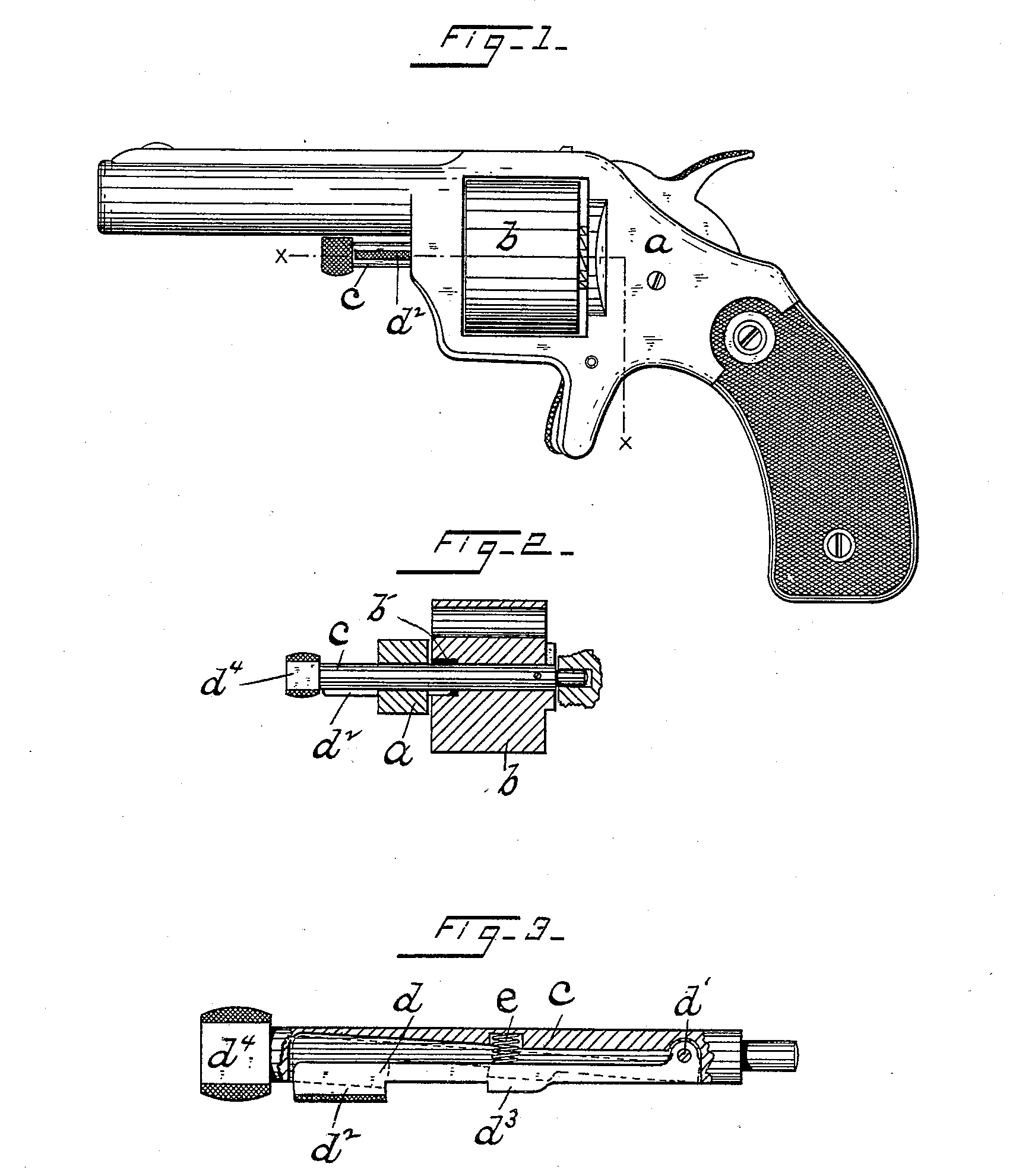
Figure 1 is a side elevation of a revolver embodying my invention and Fig.2 shows a sectional view of the frame and cylinder, substantially on line x—x of Fig. 1. Fig. 3 is an enlarged, detached, view of the axial pin of the cylinder, principally in longitudinal section, disclosing the combined latch and frictional stop which forms the essential feature of my invention.
In the drawings the letter a denotes a revolver frame, b the cylinder and c the axial pin upon which said cylinder revolves when in service. This pin is slotted lengthwise, as best seen in Fig. 3, and within the said slot is located a latch d whose rear end is pivoted within the pin c as at d’, thus permitting the forward end of said latch to be swung outward and inward a limited distance. The outer or free end of Said latch is formed with a projecting portion d^2 which may be readily engaged to press the latch down into its slot and a suitable spring, here shown as a spiral spring e, is seated within the pin and acts with a constant tendency to force the latch outward into the position shown in full lines in Fig. 3. About midway the length of the latch d is a projection d^3, which when the axial pin is in place in the frame, lies within the journal bearing of the cylinder, said bearing being counter-bored substantially as shown at b’ in Fig. 2 and the front, angular, end of said projection d^8 then lies just inside the frame, as seen in said Fig. 2, serving as a latch or catch to prevent the accidental withdrawal or displacement of said axial pin. The exposed end of the pin is flattened as at d^4 and fits closely against the under side of the barrel to prevent rotation of said pin. When the parts are thus assembled the outer face of the projection d^3 is forced by spring e into close contact with the circumferential wall of the counter-bore b’ affording sufficient frictional resistance or “drag” to hold the cylinder in a position for firing after the latter g is revolved by means of suitable pawl mechanism.
When it is desired to remove the cylinder for reloading, or cleaning, it is only necessary to press inward the projecting end d^2 of the latch when the projection d^3 is moved out of engagement with the frame and the pin c may be withdrawn from said frame.
Should it be desired for any purpose to revolve the cylinder freely without removing it from the frame, it is only necessary to press back the latch d thus throwing the projection d^3 out of frictional contact with the cylinder, when the latter may be freely revolved. It will thus be seen that I am able to provide at very small cost in one piece a lock or latch to retain the axial pin within the frame and also an effective frictional drag or stop for the cylinder.
Having thus described my invention, I claim—
In combination with the frame and cylinder of a revolving arm, a removable axial pin for said cylinder having seated therein substantially as set forth a spring-pressed latch provided with a projection d^3 that engages the inner wall of the frame to prevent the withdrawal of the pin, and also the circumferential wall of the journal bearing of the cylinder to serve as a frictional drag or stop.
JOHN ROURKE.
Witnesses:
Frank H. Allen,
Lila. D. Peale,