
US 35419
UNITED STATES PATENT OFFICE.
CHARLES W. HOPKINS, OF NORWICH, CONNECTICUT, ASSIGNOR TO HIMSELF, THOS. K. BACON, AND A. E. COBB, OF SAME PLACE.
IMPROVEMENT IN REVOLVING FIREARMS.
Specification forming part of Letters Patent No. 35,419, dated May 27, 1862.
To all whom it may concern:
Be it known that I, CHARLES W. HOPKINS, of Norwich, in the county of New London and State of Connecticut, have invented a new and useful Improvement in Revolving Fire-Arms; and I do hereby declare that the following is a full, clear, and exact description of the same, reference being had to the accompanying drawings, forming part of this specification, in which–
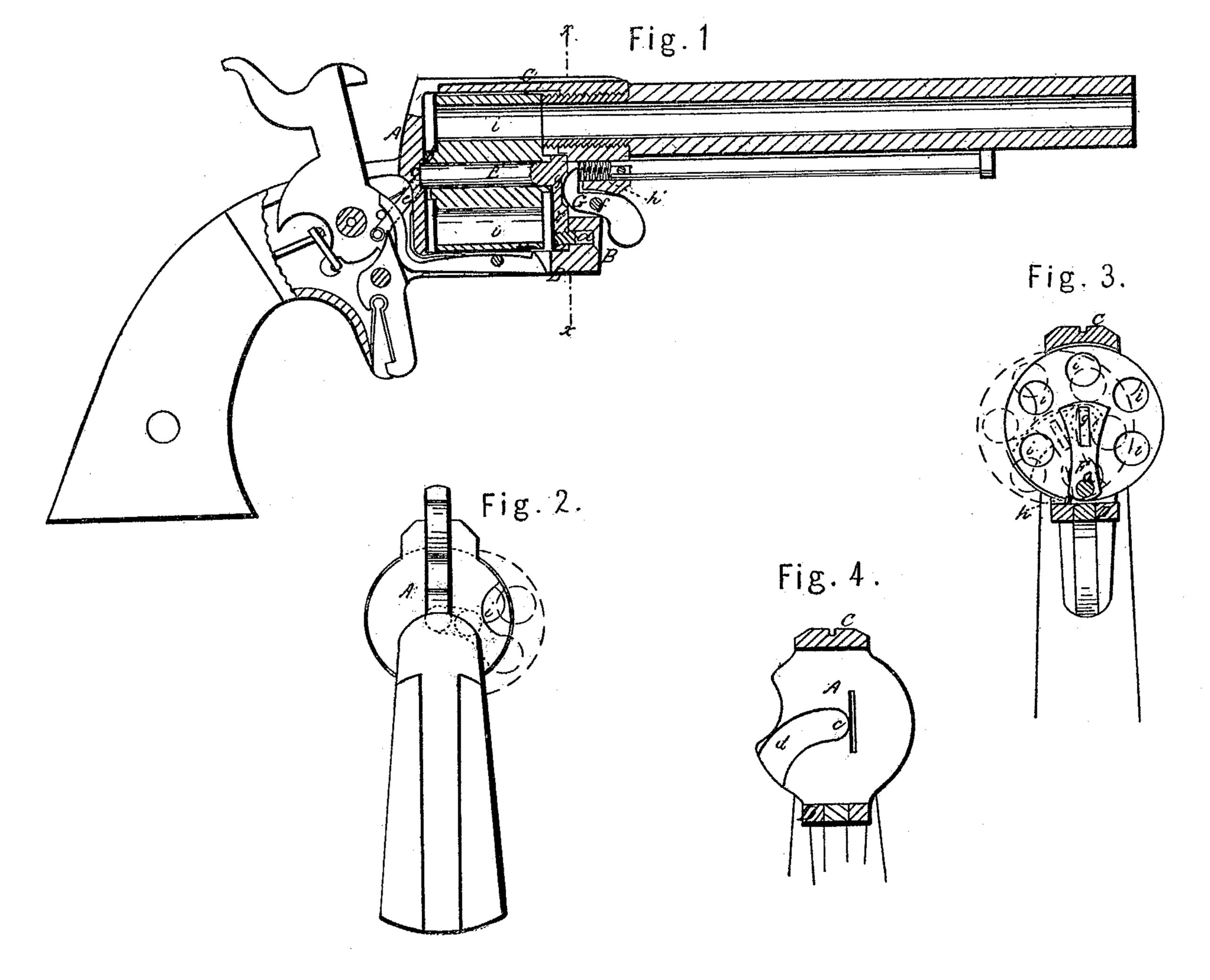
Figure 1 is a central longitudinal section of a pistol with my improvement. Fig. 2 is a back view of the same. Fig. 3 is a transverse section of the same in the line x x of Fig. 1, looking toward the cylinder. Fig. 4 is a front view of the recoil-shield.
Similar letters of reference indicate corresponding parts in the several figures.
This invention relates to revolvers having the bores, which constitute the chambers of the cylinder extended right through the rear of the latter to permit the introduction of the cartridges from the rear.
The object of the invention is to facilitate the loading of the several chambers without the necessity of taking out the cylinder from the frame or of opening the frame.
To enable others skilled in the art to make and use my invention, I will proceed to describe its construction and operation.
A B C D is the cylinder-frame, the back part, A, of which constitutes the recoil-plate or fixed breech, and which is otherwise constructed substantially in the usual manner. E is the cylinder axis-pin, and F the swinging arm, to which it is attached rigidly, and which constitutes the principal feature of my invention. This arm F, arranged within the frame A B C D, fits close against the front portion, B, of the said frame, and is attached thereto by the pin a, upon which the said arm swings, the said pin being arranged as near as practicable to the bottom of the frame. The cylinder is fitted to turn freely upon the axis-pin E, and the said pin protrudes a short distance through the rear of the cylinder and through the rotating ratchet b, formed upon the rear thereof, and the so protruding part of the pin is received within a bearing, c, provided for it in the recoil-shield. This bearing c is open to the right side of the recoil-shield, as shown at d in Fig. 4, to allow the pin to pass in and out and to permit the swinging movement of the arm F. Fig. 4 shows this opening d on the left side; but in this view the muzzle of the pistol is toward the spectator. The said opening d does not prevent the axis-pin from having a proper bearing, as the only tendency to displace the pin is that produced by the rotating doge, which presses in an upward direction.
G, Fig. 1, is a catch for locking the arm F in an upright condition, and so keeping the axis-pin in proper position to permit the chambers i i of the cylinder to be severally brought in line with the barrel by the rotation of the cylinder. This catch works through a slot in the front part, B, of the cylinder-frame upon a pin, f, inserted across the said slot, and it is pressed into a notch, g, in the arm F by means of a spring, h’; but by pressing with a finger or thumb on a portion of the said catch which protrudes through the front of the frame the said catch may be withdrawn from the notch g for the purpose of permitting the arm F to swing aside, as shown in red outline in Fig. 3, and so to carry the axis-pin and cylinder far enough in a lateral direction to allow the chambers, by turning the cylinder on the pin, to be severally and successively presented outside of the recoil-shield, as shown in Fig. 2, for the reception of the charges. The lower part of the arm F is so constructed or so provided with a stop-pin, h, Fig. 3, to come in contact with the bottom, D, of the frame that the arm will only swing aside as far as is required for loading the chambers.
To load the chambers the hammer is first placed at half-cock, to leave the cylinder free to be turned by hand, and the catch G is then pressed to liberate the arm F, which is then free to drop or to be pushed aside to the position shown in red in Fig. 3. The charges are then put in the chambers one after the other, the cylinder, after the insertion of said charge, requiring to be turned far enough to present the next chamber in position for the reception of its charge. When all the chambers have been loaded it is necessary, in order to permit replacement of the cylinder in position for firing, to let down the hammer from and a little below the position of half-cock or the rotating dog will prevent the ratchet b passing. The easing or letting down of the hammer from half-cock draws back the dog far enough for the ratchet to pass it. When the axis-pin arrives in its bearing c the catch G springs into the notch g and locks the arm F and the cylinder in place.
It is obvious that instead of placing the extremity of the axis-pin in the curved slot c the said extremity of the axis-pin might be supported in another swinging arm like that shown by F at the other end of the axis-pin.
What I claim as my invention, and desire to secure by Letters Patent, is–
The employment, in combination with the axis-pin E, of the curved slot c d and swinging arm F, substantially as and for the purpose herein shown and described.
CHARLES W. HOPKINS.
Witnesses:
SOLOMON LUCAS,
GEO. PRATT.