
US 162162
UNITED STATES PATENT OFFICE.
SULLIVAN FOREHAND AND HENRY C. WADSWORTH, OF WORCESTER, MASS.
IMPROVEMENT IN REVOLVING FIRE-ARMS.
Specification forming part of Letters Patent No. 162,162, dated April 20, 1875; application filed March 10, 1875.
To all whom it may concern:
Be it known that we, SULLIVAN FOREHAND and HENRY C. WADSWORTH, of the city and county of Worcester, and Commonwealth of Massachusetts, have invented certain new and useful Improvements in Revolving Fire-Arms; and we do hereby declare that the following is a full, clear, and exact description of the same, reference being had to the accompanying drawings forming a part of this specification, and in which–
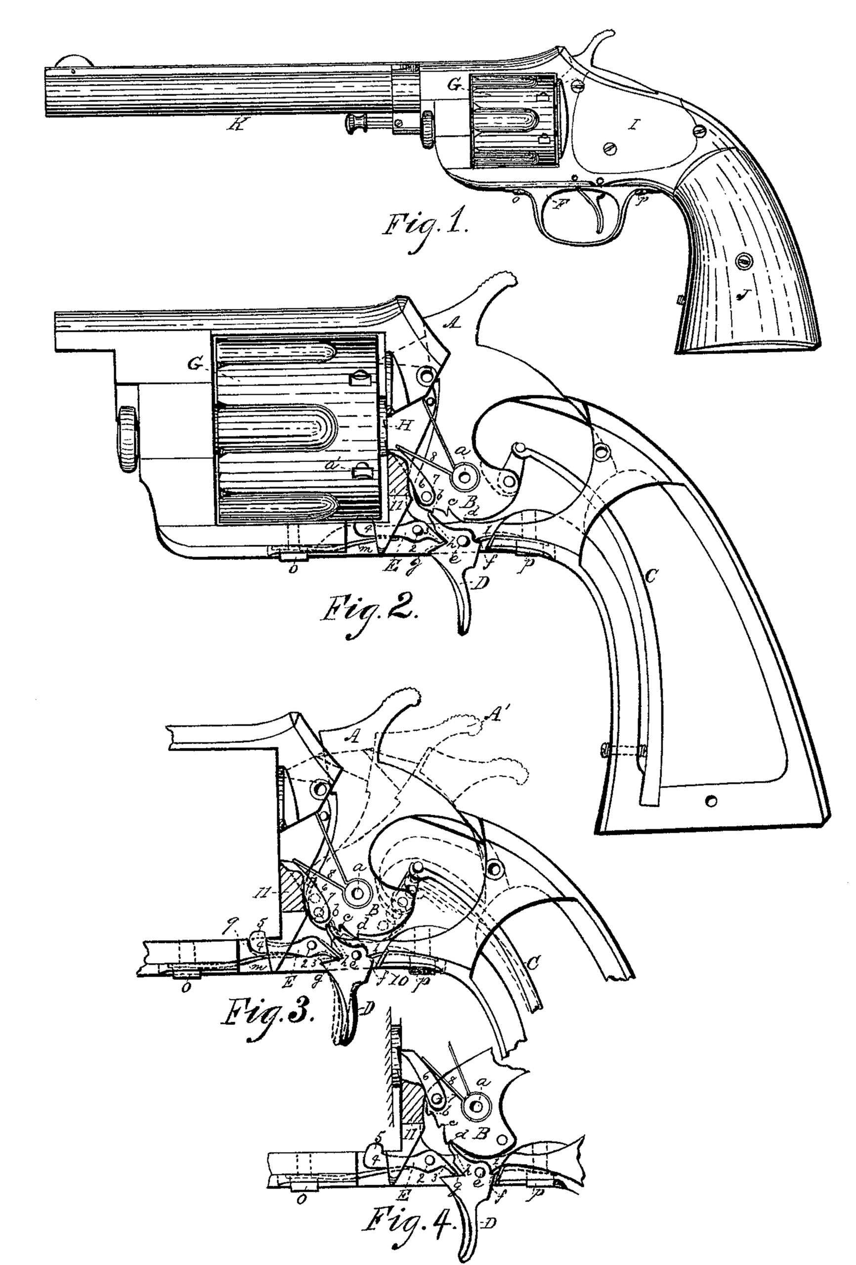
Figure 1 represents a side view of a revolving fire-arm with our improvements applied thereto. Fig. 2 represents, upon an enlarged scale, a side view of a portion of said arm, some of the parts being shown in section and some of the parts being removed, to illustrate more fully the operation of our present improvements. Fig. 3 also represents, upon an enlarged scale, a side view of some of the parts shown in Fig. 2, the parts being shown in different positions in full and dotted lines; and Fig. 4 also represents, upon an enlarged scale, a portion of the parts shown in Figs. 2 and 3, but in different positions, as will be hereafter more fully explained.
To enable those skilled in the art to which our invention belongs to make and use the same, we will proceed to describe it more in detail.
In the drawings, Fig. 1 represents a side view, in its general construction, of a revolving fire-arm, known as that manufactured heretofore by the firm of Ethan Allen & Co., and, since the decease of said Allen and dissolution of said company, by Sullivan Forehand and Henry C. Wadsworth, the joint inventors of the improvements herein named. One of the important features of said fire-arm is that for which Letters Patent Were granted to the said Ethan Allen on the 22d day of October, 1861, and upon which invention our present one is an improvement. By said Allen’s patented improvement, when the pistol was cocked, a stop-spring forced the end of a lever stop down until it rested upon a projecting part of the trigger, while the opposite end of the stop-lever was forced into a recess of the revolving cylinder, which was thereby locked and securely held in the right position to be discharged. There was, however, an objection to that arm as thus constructed, which was that the nose of the hammer necessarily rested against the base of the cartridge-case, unless it was at half or full cock; consequently, it will be seen, that if the loaded arm was carried with the hammer down, there was a liability of its being prematurely discharged by some sudden blow or jar; and the nature of our invention consists in the combination of the tumbler, trigger, and lever-stop under such a construction and relative arrangement of the parts that the hammer may be slightly withdrawn, so as to lift or remove its nose from contact with the base of the cartridge shell, while at the same time the lever-stop holds and locks the cylinder, and keeps it from being turned in either direction as securely as it does when the hammer is at full cock.
In the drawings the part marked A is the hammer, and B the tumbler, both pieces being made from a single piece of metal, the tumbler being hinged at a. The lower edge of the tumbler is made in a peculiar manner, and with three notches or teeth, b, c, and d, the middle notch c being set in or out of line with the notches b and d. C is the mainspring, combined with the rear of the gun and tumbler in the usual manner. D is the trigger, pivoted at e, and provided with a shoulder, f, against which the end of spring 1 presses, and with notch g and finger or dog h, to catch into the notches b, c, and d. E is a stop or locking lever, pivoted at 2, with its rear end 3 resting in the notch g, while its front end 4 is bent up or formed in hook-shape, as indicated in the drawings at 5. The front end of the stop-lever E is pressed up by a spring, m, said spring being of less force or power than the spring I. The springs m and 1 are held in place by screws o and p; the same screws also fasten the guard F in place, as shown in Fig. 1, the guard being removed or not shown in Figs. 2, 3, and 4, for the purpose of showing the operation of the working parts more fully. G is the revolving cylinder, provided with a ratchet-hub, H, by means of which it is revolved by the pawl 6, pivoted at 7 to tumbler B, and held to its place by spring 8. A portion of the under side of the frame is, in Fig. 3, shown cut away at 9 10, and a portion of the breech-piece at 11, for the purpose of showing the working parts more fully. In Fig. 2 the hammer is shown down as it appears after the charge has been exploded. In Fig. 3, in full lines, hammer A is shown drawn back, so that finger h will catch into the safety-notch b in the tumbler B, and while in this position cylinder G is securely locked by the projection 5 taking into one of the notches a’ in the cylinder G, and when in this position the arm can be safely carried about, since the point or nose of the hammer is withdrawn from contact with the base of the cartridge shell or case. The positions of the hammer at half and full cock are also shown by dotted lines in same figure. When the hammer is at half-cock, as shown at A’, Fig. 3, finger h will drop into notch c in tumbler B, while spring 1, being stronger than spring m, will force the lower end of trigger D forward, as shown in dotted lines, Fig. 3, thereby forcing up the rear end 3 of locking-lever E, while the front end 4 and spring m are forced down, so as to withdraw projection 5 below the lower surface of the cylinder G; consequently it will not catch into the notches a’ in the cylinder and prevent the latter from being turned. When the parts are in these positions cylinder G can be turned forward for the purpose of removing the exploded shells and reloading the arm, pawl 6 preventing the cylinder from being turned back. In Fig. 4 tumbler B, trigger D, finger h, and locking-lever E are shown in the positions which they occupy when the arm is at full cock.
It will be noticed by reference to Fig. 4 that notch g is made a little larger than the rear end 3 of lever E; consequently, when hammer A is drawn back to allow finger h of trigger D to fall into the safety-notch b, the slight forward motion of trigger D is not sufficient to impart any great motion to the rear end of lever E, and consequently projection 5 still remains sufficiently high to keep the cylinder G locked.
Having described our improvements in revolving fire-arms, what we claim therein as
new and of our joint invention, and desire to secure by Letters Patent, as an improvement On the invention patented to Ethan Allen under date of October 22, 1861, is–
The combination, with tumbler B and cylinder G, of safety-notch b, trigger D, finger h, locking-lever E, and springs 1 and m, substantially as and for the purposes set forth.
SULLIVAN FOREHAND,
HENRY C. WADSWORTE.
Witnesses:
EDWIN E. MOORE,
ALBERTA BARKER.