
US 179026
UNITED STATES PATENT OFFICE.
OWEN JONES, OF PHILADELPHIA, PENNSYLVANIA.
IMPROVEMENT IN CARTRIDGE-EXTRACTORS FOR REVOLVERS.
Specification forming part of Letters Patent No. 179,026, dated June 20, 1876; application filed May 31, 1876.
To all whom it may concern :
Be it known that I, OWEN JONES, of Philadelphia, in the county of Philadelphia and
State of Pennsylvania, have invented new and useful Improvements in Cartridge Extractors; and I do hereby declare that the following is a full and exact description of the same, reference being had to the accompanying drawings, and to the letters of reference marked thereon.
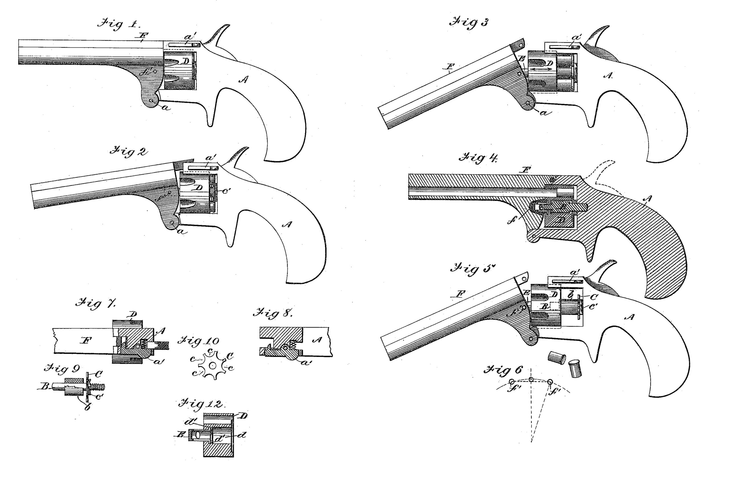
In the drawings, Figure 1 represents a side elevation of a pistol when loaded ready for
use; Fig. 2, a side elevation, representing the beginning of the movement for extracting the
cartridges; Fig. 3, a similar view with the movement about completed; Fig. 5, a similar view with the cartridges out; Fig. 4, a sectional elevation, showing the internal construction; Fig. 6, a view illustrating the movement of the pin and link connecting the barrel to the cylinder; Figs. 7 and 8, views of the locking-catch and hammer-head; and Figs. 9, 10, 11, and 12, views of different parts detached.
To enable others skilled in the art to make and use my invention, I will now proceed to
describe fully its construction and manner of operation.
This invention consists mainly, first, in the combination, with a relatively stationary extractor and a sliding cylinder, of a hinged barrel and intermediate connecting devices, uniting the barrel to the cylinder, the construction being such that when the barrel is tilted on its hinge the cylinder is drawn forward by the intermediate connecting devices, and the cartridge-shells held by the stationary extractor are consequently left unsupported and fall to the ground; second, in the employment of an intermediate link, or equivalent device, to unite the tilting barrel to the sliding cylinder, the construction being such that the movement of the barrel in the arc of a circle is communicated to the cylinder moving in a horizontal plane without strain or undue friction.
It consists, further, in certain details of construction, which, in connection with the foregoing, will be fully described hereinafter.
A represents the frame or stock of the pistol, constructed generally in any proper manner, but provided, essentially, with a hinge, a, by means of which the barrel F is attached, and a catch, a’, of any suitable construction, by means of which the barrel is properly locked when in its normal position. B, Figs. 4 and 9, represents the center-pin, of suitable length and size, which projects from the frame into proper position to receive the cylinder, as shown. b represents a sleeve or collar, which either forms a part of the center-pin, or is rigidly attached thereto, as far as longitudinal movement is concerned, as shown. This is preferably extended in length to furnish a proper bearing-surface for the cylinder in its longitudinal movement. C, Figs. 9 and 10, represents the cartridge-extractor, consisting of a disk of proper size, located upon the center-pin in rear of the collar b, which is provided with a peripheral series of recesses, c, adapted to receive and hold the cartridges in the usual well-known manner, and also with rearward-projecting series of ratchet teeth c’, adapted to be acted upon by the usual mechanism for revolving the cylinder. D represents the cylinder, constructed generally in the usual well-known manner, but provided with a central recess, d, adapted to receive the center-pin and its collar, and an annular groove, d’, adapted to hold the flange of the sleeve-link, as shown. E, Figs. 4, 11, and 12, represents the sleeve-link, consisting of a cylinder made preferably of spring-steel, which is provided with flanges e at one end, and has also longitudinal slots e1 upon its sides, and the transverse slots e2, as shown. This sleeve link is attached to the cylinder by compressing its slotted end, and inserting it into the central opening until the flanges e are in line with the corresponding groove d’, as shown. F represents the barrel, hinged to the frame, as shown, which is provided with a central recess, f, adapted to receive the projecting end of the sleeve-link, and a transverse pin, f’, which passes through the transverse slots of the link, and thus unites the cylinder and barrel together.
The hinge of the barrel, it will be observed, is located upon a line equidistant between the limit of movement of its pin f’ in either direction, as shown in Fig. 6, so that when the barrel is tilted this point or pin, to which the sleeve-link is attached, moves in equal arcs upon each side of the central line, and hence varies less from the horizontal plane in which the cylinder moves than would be possible if the pivot or hinge were located at any other point. The entire length of this movement properly corresponds with the length of the cartridge to be extracted, the distance upon each side of the line equaling, of course, one half of the cartridge length.
a’, Figs. 1, 7, and 8, represents the spring catch for locking the barrel when in its normal position. This is constructed, generally, in any proper manner, but has essentially its rear portion so formed as to project past the hammer-head when the latter is in position to explode the cartridge, as shown in Fig. 7, so that movement to unlock the barrel is impossible until the hammer-head, which lies in its path of movement, has been removed, as shown in Fig. 8.
The extractor may be held from longitudinal movement on the center-pin, if desired, this play being preferred for small sizes; but it may also be permitted to slide with the cylinder some distance, as shown in Fig. 9, in order that an impetus may be given to the cylinder and barrel before the extractor acts (in consequence of striking the collar) to hold the cartridge-shells, this impetus being desirable in order that jammed or tightly-held shells may be readily removed.
When this construction is employed the hinge-pivot is moved forward a proper distance, so that the barrel may tilt, as before described, upon a point equidistant between its limits of movement.
The operation of my invention is as follows: The general operation of the pistol is, of course, similar to others of its class. The extracting mechanism acts in the following manner: The cartridges having been inserted in the cylinder in the usual manner, and the pistol having been fired, the entire series of shells may be extracted at a single operation by simply unlocking the barrel and tilting it on its hinge. By means of this action the cylinder, which is united to the barrel by the sleeve link, is, of course, moved forward upon the center-pin. The cartridges, however, being held from forward movement by the extractor, are consequently left unsupported and fall to the ground. The cartridge-extractor is loose upon the center-pin, but connection is made between it and the cylinder by means of the cartridges, so that the latter is properly revolved by the usual mechanism employed for that purpose.
Some of the advantages of the described construction are as follows: The construction of the parts is exceedingly simple, and yet the mechanism is very effective in its action. The barrel is employed as a lever to extract the cartridges, and hence their removal is effected without difficulty. By locating the hinge of the barrel upon a central line, between the limits of its movement, the cylinder may be attached to it by an intermediate connection, having but little play from a longitudinal line.
The construction of the sleeve-link is advantageous, because it may be readily sprung into place, or removed therefrom when desired. By means of its construction, also, the sleeve is adapted to receive the end of the center-pin, and thus hold the barrel and cylinder accurately in line with each other.
I do not limit myself to the sleeve-link for uniting the barrel to the cylinder, as other means of making this connection will be readily suggested to the skilled mechanic.
Having thus fully described my invention, What I claim as new, and desire to secure by Letters Patent, is–
1. The combination of a fixed center-pin, a relatively fixed extractor, and a sliding cylinder with a tilting barrel and mechanism for connecting the barrel to the cylinder, the construction being such that the cylinder is adapted to slide upon the center-pin, but is held from removal from it, substantially as described.
2. In combination with a tilting barrel and a cylinder sliding upon a center-pin, intermediate connecting devices, uniting the two parts together, so that the movement of the former is communicated to the latter without lost motion, substantially as described.
3. The combination of the following elements: a fixed center-pin, a cylinder adapted to slide upon the center-pin, and a lever-barrel adapted to actuate the cylinder, substantially as described.
4. In combination with the center-pin, the sliding cylinder, the longitudinally-moving
extractor, and the stop-collar, the barrel adapted to actuate the cylinder, as described.
5. In combination with the grooved cylinder, the slotted and flanged sleeve-link, as described.
6. The combination of the center-pin and sleeve-link with the barrel and cylinder, as described, the former being adapted to hold the latter accurately in line, as set forth.
7. The combination of the locking-catch with the hammer-head, the former being held
from accidental movement by the latter, substantially as described.
This specification signed and witnessed this 27th day of May, 1876.
OWEN JONES.
Witnesses:
H. W. BEADLE,
WILLIAM FITCH.