
US 32333
UNITED STATES PATENT OFFICE.
CHARLES R. ALSOP, OF MIDDLETOWN, CONNECTICUT, ASSIGNOR TO J. W. ALSOP, OF NEW YORK, N.Y.
IMPROVEMENT IN REVOLVING FIRE-ARMS.
Specification forming part of Letters Patent No. 32,333, dated May 14, 1861.
To all whom it may concern:
Beit known that I, Charles R. Alsop, of Middletown, in the county of Middlesex and State of Connecticut, have invented certain new and useful Improvements in that class of Fire-Arms known as “Revolvers;” and I do hereby declare that the following is a full, clear, and exact description of the same, reference being had to the accompanying drawings, forming part of this specification, in which—
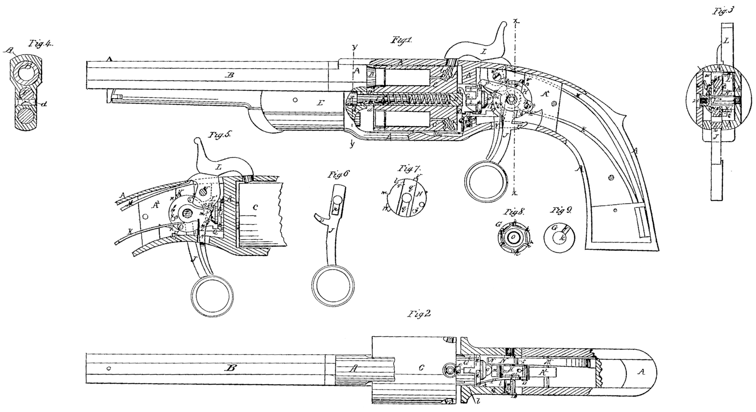
Figure 1 is a side view, partly in section, of a pistol with my improvements. Fig. 2 is a top of the same, also partly in section. Fig. 3 is a transverse section of the same in the plane indicated by the line x x of Fig. 1. Fig. 4 is a transverse section of the same in the plane indicated by the line y y of Fig. 1. Fig. 5 exhibits an opposite side view of the lock and the cocking and revolving mechanism to that exhibited in Fig. 1. Figs. 6, 7, 8, and 9 are views of some of the details which will be hereinafter explained.
Similar letters and numbers of reference indicate corresponding parts in the several figures.
My invention relates to those revolvers in which a many-chambered cylinder rotates on an axis parallel with the bore of a stationary barrel.
It consists in certain improvements in the means of obtaining a longitudinal movement of the many-chambered cylinder for the purpose of forcing it up tightly against the barrel to make a tight joint there with at the time of firing, and of drawing it back out of contact therewith previous to its rotary movement.
It also consists in certain improvements in the mechanism for effecting the cocking of the hammer and the rotation and stoppage of the cylinder, and in the mode of applying the trigger.
A is the metal frame, of the form generally adopted for the frames of revolvers. B is the barrel. C is the cylinder, fitted to revolve on the axis-pin D, which is of a length to enter some distance into the front part of the frame A and to extend a short distance through the rear of the cylinder, as shown in-Fig. 1. The said pin has its front portion a little enlarged to form a shoulder, a a, to bear against the front of the cylinder, and it is bored out cylindrically from the front end for a considerable portion of its length to receive within it a spiral spring, b, and a portion of a pin, F, which is formed on the rear of the rammer-shell E, and which passes through the front portion of the frame A, the said pin F being secured rigidly in the frame by a transverse pin, d, and serving to attach the rammer-shell to the frame. The axis-pin is attached to the aforesaid pin F by a small pin, c, passing through a hole drilled in the axis-pin D and a notch, e, cut in the said pin F, the said notch being long enough to allow a limited longitudinal movement of the axis-pin-upon the said pin F. The portion of the axis-pin E which projects through the rear of the cylinder enters and fits snugly into a hole, k, in the front of a cylindrical piece, G, which fits up against the rear of the cylinder and fits to a bearing in the cross-piece A’ of the frame.
In the front face of the piece G there is a radial groove,f, (shown in section in Fig. 1, and shown also in Fig. 9, which is a front view of the said piece,) said groove receiving a pin, g, which projects from the rear of the cylinder, and so causing the cylinder and the said piece G to rotate together. In this way the said piece G. is made to constitute a rear journal to the cylinder. In the rear of the said piece G. there are formed the series of ratchet-teeth h h, (shown in Fig. 8, which is a back view of the said piece,) such teeth being operated upon, as hereinafter described, to produce the revolution of the cylinder; and in front of these teeth there is a series of stop-notches, i i.
The cylinder axis-pin D is secured against any lateral oscillation by its front end being fitted into the front part of the frame A and onto the fixed pin F and its rear end being fitted into the journal-piece G, and the said pin is prevented turning with the cylinder and the journal-piece G by the pin c, before mentioned. The spring b, that is arranged within the axis pin, acts between the rear of the bore of the said pin and a shoulder, j, on the pin F, with a constant tendency to force back the axis-pin, and the shoulder a a on the said pin exerts a constant tendency to force back the cylinder away from the barrel as far as is permitted by the means employed to force the cylinder to ward the barrel, which will be presently described, the notch e allowing the axis-pin to move longitudinally independently of the pin F.
The attachment of the axis-pin to the pin F by the pin c enables the former to be withdrawn from the cylinder through the front of the frame by drawing out the shell of the rammer, which is liberated by turning the transverse pin d, and the mode of applying the spring always leaves it attached to the axis-pin, so that it cannot be lost, besides keeping it unexposed to dirt.
H, Figs. 1,2,5, and 7, is a cam applied in rear of the journal-piece G for the purpose of forcing forward the cylinder. The said cam, which is bored centrally to fit loosely on a fixed pin, I, arranged transversely to the frame and stock, has about seven-eighths of its circumference circular and concentric with its central bore, and the remaining portion is a recess, l m. Behind the said cam there is cast with or otherwise firmly secured between the top and bottom of frame A a stout brace, A^2, which, to express the purpose, I call the “recoil-block,” the front of which is hollowed out, as shown at n n in Figs.1 and 5, to form a bearing for the cam H, which fits the pin I so loosely as to permit of its always resting in the said bearing.
The journal-piece G is furnished at the center of its rear with a rounded knob, o, which is always held against the periphery of the cam H by the pressure of the spring by before described. The full diameter of the larger circular portion of the said cam is such that when interposed between the bearing n n and the knob o while one of the chambers of the cylinder is opposite the barrel the said cam will hold the cylinder forward toward the barrel very firmly, with the conical seat which is formed round the chamber in the front of the cylinder in close contact with the valve-like seat that is formed round the rear muzzle of the barrel; and the recess l m need only be of such depth that when it is presented opposite to the knob o it will allow the cylinder to be pushed back by the spring b just far enough for the cylinder to clear the rear end of the barrel. The cam H has connected with it the finger-lever J, by which the cocking of the piece is effected, the said lever, of which Fig. 6 is a side view, having formed upon it a tenon, p, which is received into a deep mortise, q, (see Fig. 7,) in one side of the cam, and being fitted also into a shallower mortise, q’, in the same side of the cam. The pin I, which enters the frame from the left hand and screws into a solid part, A^3, of the frame at the right side of the stock, as shown in Figs, 2 and 3, passes through the cocking-lever J and fits up to the outer side of it with a shoulder, r, and so secures the said lever to the cam.
On the opposite side of the cam to that on which the cocking-lever J is attached there are two projecting studs, s and t, which may be made of the solid metal or screwed in, the up per studs, being for the purpose of cocking the hammer, as Will presently be explained, and the lower stud, t, serving as a bearing for the spring K, which is secured within the stock, and which by its downward pressure on the said stud tends to turn the cam in the direction of the arrow 10 shown on it in Figs, 1 and 5, and so to throw forward the cocking-lever. When the lever is left free the cam is stopped by a stop-pin, v, on its periphery coming in contact with the upper part of the recoil-block A in such a position that the recess l m is immediately above the knob o, and the full circular portion of the cam bears against the said knob, and so keeps the cylinder forward in contact with the barrel, the cylinder in such condition of the cam always having one of its chambers opposite to the barrel. As the cocking-lever is pulled back the edge an of the recess l m passes the knob o and allows the spring b to force back the cylinder; but on the liberation of the cocking-lever the spring K returns the can to the first-mentioned position, and in such return the beveled edge on of the recess l m, by its action upon the knob o, forces forward the cylinder. The cocking-lever is furnished with a projection, 21, which comes in contact with the recoil-block and acts as a stop to prevent the lever being pulled too far back.
L is the hammer, working on a fixed pin, w, above and a little in front of the pin I, and having its butt L’ arranged on one side of the cam H. The lower part of the butt L is situated in front of the studs, so that as the cocking-lever is drawn back the said stud presses forward the portion of the butt below the pin w and throws back the upper part of the hammer. This mode of applying the cocking-lever leaves the hammer free to be cocked by the direct application of pressure to the hammer itself. The hammer-butt has the usual notches, 18 and 19, for full-cock and half-cock.
M is the mainspring, the mode of whose application is one which is commonly used, as shown in the drawings, and needs no explanation.
N is the trigger, whose form is best represented in Fig. 5. This is fitted to work on the pin I, and carries its own sear, N’.
Z is the trigger-spring, attached to the trigger and working between the back of the finger-piece thereof and back of the slot in the frame through which the trigger works.
P is the dog, which operates upon the ratchet teeth. h. h. to produce the rotary motion of the cylinder, said dog consisting of a lever, which works upon the pin I as its fulcrum, the said lever being elastic in a lateral direction. The rear end of the said lever is provided with a slot, 12, to receive a pin, 13, that is screwed into or otherwise firmly secured to the cam, and the said pin, acting against the upper end of the slot 12 when the cocking-lever is drawn back, raises the rear end of the said lever and causes the depression of the front end upon one of the ratchet-teeth h h, and so produces the necessary amount of rotary motion of the cylinder, the said slot 12 being just long enough to allow sufficient play of the pin 13 within it when the drawing back of the cocking-lever commences to permit the edge m of the recess in the cam l m to pass the knob o, and so permit the cylinder to move back, as well as to enable the hammer to be raised off the nipple and the cylinder to be unlocked before the dog begins to operate on the ratchet-tooth to produce the rotary motion of the cylinder.
The means by which the cylinder is locked at the time of firing and unlocked to permit its rotary motion have not yet been described; but I will now proceed to describe them.
Q is the locking-piece, consisting of a bent lever arranged to work on a pin, 14, that is secured in the frame A below the cylinder, and passing through a slot in the lower part of the bearing of the journal-piece G. The said lever is furnished with a tooth, 15, to enter the notches i i in the journal piece G, and its rear end, which is beveled on its upper side, is situated near the cam H.
16 is a small spring applied in a cavity in the frame A below the dog, and acting upon the said dog to press its tooth 14 into contact with the journal-piece.
17 is a wiper projecting from the periphery of the cam H. some distance below the recess l m. As the cocking-lever is drawn back the wiper 17 passes over the beveled rear portion of the lever Q, and so depresses it sufficiently to remove the tooth 15 from the lower notch, i, of the journal-piece G, and holds it so depressed during the rotary motion of the cylinder; but as the movement of the cocking-lever is completed, by which time a new notch, i, has been brought opposite the tooth 15, the wiper escapes past the end of the lever Q and allows it to be forced quickly upward by the spring 16 into the new notch and stop any further rotation of the cylinder. As the cocking-lever is returned by the spring K to its forward position on the liberation of the cocking-lever, the wiper 17, being properly beveled in front for the purpose, passes the lever Q by depressing it; but as the said lever Q arrives in its forward position the wiper passes over the top of its beveled extremity and allows it to spring up again into the notch to lock the cylinder, and in this condition the said lever Q remains while the piece is fired and until the cocking-lever is again drawn back.
The pin I, besides serving as the axis for the cocking-lever, the cam H, and the revolving lever P, serves to attach the side plate, Q, of the stock. The said pin is made too short to extend all the way through the said plate, but long enough to enter a hole provided in the said plate to fit it. The said hole is countersunk on the outside of the plate to receive the head of a screw, 20, which screws into a tapped hole in the end of the pin I, and so secures the said plate to the frame. The said plate also serves as a bearing to prevent the lateral displacement of the pin, as it is fitted to the frame with suitable lugs or steady-pins. By thus applying the plate Q in combination with the pin I, the said plate is made to form a bearing for the pin and to form a means of attaching the plate, and the said plate is permitted to be removed without disturbing the pin.
Instead of the cam H being formed, as described, with a recess, lm, the front part may be of regular eccentric curved form; and instead of the can being a complete circle, as represented, it may be only a segment; but whatever its form it should have a bearing in the recoil-block A^2, and not depend upon the pin I to sustain the recoil.
Having thus described my invention, I will proceed to state what I claim as new, and desire to secure by Letters Patent—
1. Combining the oscillating cam H with the cocking-lever, so as to be operated by and with the said lever to permit the backward longitudinal movement of the cylinder, substantially as herein described.
2. The spring K, applied and operating in combination with a stud or projection, t, on the side of the oscillating cam H, to produce the necessary movement of the said cam to give the cylinder its forward longitudinal movement, substantially as herein set forth.
3. Effecting the cocking of the hammer, by means of a stud or projection, s, on the side of the oscillating cam El, substantially as here in specified.
4. Placing the spring b, by which the backward longitudinal movement of the cylinder is produced, within the axis-pin itself, substantially as and for the purpose herein specified.
5. Combining the axis-pin D with the pin F, which attaches the rammer-shell to the frame A, by means of the spring b, the pin c, and the notch e, all applied and operated substantially as herein described.
6. The hanging of the trigger and sear on the axis-pin of the cam, by which the forward longitudinal movement is produced, substantially as herein described.
7. The hanging of the cocking-lever J on the axis-pin of the cam, by which the forward longitudinal movement of the cylinder is produced, substantially as herein described.
8. The employment of the same pin, I, as the axis of the cam H. and the fulcrum of the cocking-lever, the trigger, and the revolving lever or dog, substantially as herein specified.
9. Combining the axis-pin I of the cam, by which the forward longitudinal movement of the cylinder is produced, with the movable side plate of the stock by means of the countersunk hole in the said plate, and the screw 20, passing through the said plate and screwing into the said pin, substantially as and for the purpose herein described.
10. Making the locking and stop notches i i in the periphery of the rear journal of the rotating cylinder, substantially as herein described.
CHAS, R, ALSOP.
Witnesses:
Jas. E. Lathrop,
Jonathan Barnes.