
US 30990
UNITED STATES PATENT OFFICE.
HORACE SMITH AND DANL. B. WESSON, OF SPRINGFIELD, MASSACHUSETTS.
IMPROVEMENT IN REVOLVERS.
Specification forming part of Letters Patent No. 30,990, dated December 18, 1860.
To all whom it may concern:
Be it known that we, Horace Smith and Daniel B. Wesson, of Springfield, in the county of Hampden and State of Massachusetts, have invented new and useful Improvements in Revolving Fire-Arms; and we do hereby declare that the following is a full, clear, and exact description of the construction and operation of the same, reference being had to the accompanying drawings, making a part of this specification, in which—
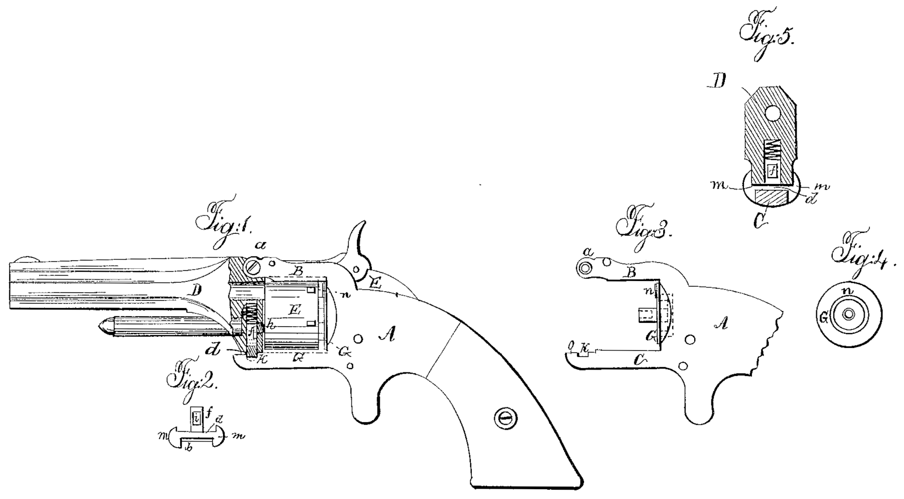
Figure 1 represents a side view of one of our pistols with our improvements attached, it being partly in section to show the construction more clearly. Fig. 2 is a front view of the thumb-catch, detached from the rest of the implement. Fig. 3 is a side view of a portion of the lock-frame, showing more clearly the form and position of the recoil-shield. Fig. 4 rep resents a front view of the recoil-shield; and Fig. 5 represents a transverse section on the line x x of Fig.1, showing the arrangement of the thumb-catch to prevent lateral movement of the barrel.
One part of our improvement in revolving fire-arms relates to those in which a revolving cylinder is used with the chambers to receive the charge extending entirely through the revolving block, and are covered at the rear by a recoil-plate. The great objection to this description of arms as at present constructed is that only sufficient space is left between the recoil-plate and the rear of the revolving block to receive the head of the cartridge, and when metallic cartridges are used the bulging out of the base after being fired causes the cartridge to press against the recoil-plate and impede the movement of the cylinder.
The object of one part of our invention is to overcome this defect; and our invention for effecting this object consists in a recoil plate or shield covering all the chambers of the revolving block, and arranged a sufficient distance back of the revolving block to prevent the cartridge jamming after being fired, in connection with a projection on the shield directly in rear of the cartridge when in position to be fired, so as to hold it firmly against the revolving block while being fired. Another part of our invention relates to those arms in which the barrel is hinged to the lock-frame, so that it may be raised or turned back to withdraw the cylinder or insert the charge; and the object of this part of our invention is to simplify the mechanism for holding the barrel down against the revolving cylinder, give to it increased security, and also greater facility to release or fasten the barrel down; and our invention to effect this object consists in the application of a spring-catch to the barrel, so arranged as to hold the barrel down and also to hold it laterally, that the axis of the barrel may be retained in line with the axes of the chambers in the revolving block when in position to be fired.
Our improvements will be more fully understood by reference to the accompanying drawings, in which A is a metallic lock-frame, with two straps, B and C, projecting forward to receive the barrel D and hold it in proper position. E is a revolving cylinder, with the chambers extending entirely through the block to receive the charges at the rear. This block is revolved by mechanism operating by the hammer F in the usual manner. The barrel is connected to the strap B by a hinge joint, a, on which it turns, and is held down by means of a thumb-catch, b, which springs into a recess, K, in the lower strap, C. This thumb-catch consists of a cross-bar, d, with projections M at either end extending beyond the upper and the lower face of the bar, and the distance between these projections on either side corresponds respectively with the thickness of the strap C and the projection c of the barrel at the point where the projections m of the catch embrace both of these parts, in order to prevent the barrel moving laterally.
Extending from the upper side of the catch is a stem, f, which enters a hole, e, in the projection c of the barrel exactly corresponding in diameter with the stem, in order to prevent lateral vibration in the catch; and in this hole is also inserted a spiral spring, g, to act on the stem, and holds the catch in the notch R of the strap C. A small set-screw, h, holds the catch to the barrel. In rear of the cylinder E, and attached to the lock-frame, is a stationary recoil-shield, G, to receive the recoil of the charge when ignited.
The shield consists of a flat disk connected with the lock-frame; or it may be made solid with it, and of sufficient size to cover all the chambers in the revolving cylinder. On its face is a projection, n, arranged in such position as to be directly in rear of that cartridge or charge which is in position to be fired, in order to hold the cartridge in close contact with the cylinder while being fired, and leave sufficient space between the other parts of the shield and the cylinder that the bulging out of the rear of the cartridge after it has been fired will not cause it to jam between the shield and the cylinder, and thus impede the free revolution of the latter.
It will be seen from the construction and arrangement of the spring-catch to hold the barrel down that it is not only held securely by this catch from rising up, but that, the projections on the ends of the catch overlapping the projection on the barrel and the lower strap of the lock-frame, all tendency to lateral movement in the barrel is prevented, so that the axis of the barrel retains its position in line with the axes of the chambers of the cylinder when brought in proper position to be fired, while at the same time the barrel is released with the greatest facility, so that it can be turned back to remove or charge the cylinder.
It will also be seen from the construction of the shield with a projection on its face, as described, that the cartridge, when fired, is nearly in contact with this projection, which receives its recoil, and that the turning of the cylinder brings a new cartridge in the place of the one exploded, which is carried past the projection into the open space between the shield and the cylinder, which is sufficiently wide to accommodate any bulging out of the base of the cartridge that may have been produced by its being exploded.
As the face of the shield from the projection is a plane unbroken surface, on which the head of the cartridge is not liable to catch, and as there is sufficient space between the shield and the cylinder to accommodate the bulging out of the base of the cartridge after being fired, no impediment is offered, as in other stationary shields, to the free revolution of the cylinder after the cartridges are fired.
Having thus described our improvements in revolving fire-arms, what we claim as new, and desire to secure by Letters Patent, is—
1. The combination of a revolving cylinder having its chambers extending entirely through the block with an unbroken recoil-shield having a projection on its face, as described, for the purpose set forth.
2. The combination of the barrel hinged to the lock-plate with a spring-catch, b, arranged with end projections to grasp the barrel and plate, substantially as described, for the purpose as set forth.
In testimony whereof we have subscribed our names.
HORACE SMITH.
D. B. WESSON.
Witnesses:
J. M. Hall,
N. B. Clarke.