
US 30843
UNITED STATES PATENT OFFICE.
EBEN T. STARR, OF NEW YORK, N.Y.
IMPROVEMENT IN REVOLVERS.
To all whom it may concern:
Be it known that I, EBEN TOWNSEND STARR, of the city, county, and State of New York, have invented certain new and useful Improvements in that class of Fire-Arms known as “Revolvers;” and I do hereby declare that the following is a full, clear, and exact description of the same, reference being had to the accompanying drawings, forming part of this specification, in which—
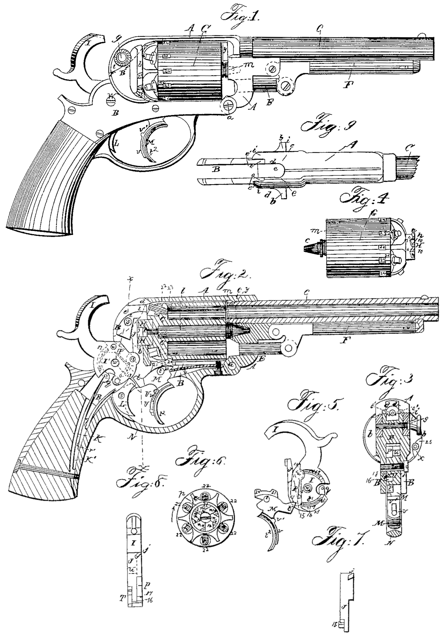
Figure 1 is a side view of a pistol with my improvements. Fig.2 is a longitudinal section of the same. Fig. 3 is a transverse section of the same in the line x x of Fig. 2. Fig. 4 is a side view of the many – chambered cylinder. Fig. 5 is a side view of the mechanism of the lock. Fig. 6 is a back view of the cylinder. Fig. 7 is a front view of the dog, by which the revolving of the cylinder and the stopping of the same in proper position are effected. Fig. 8 is a front view of the hammer with the cocking and revolving dogs attached. Fig. 9 is a top view of the cylinder-frame.
Similar letters and numbers of reference indicate corresponding parts wherever they occur in the several figures.
To enable others skilled in the art to make and use my invention, I will proceed to describe its construction and operation.
A B represent the cylinder-frame, having the stationary barrel C screwed into the upper part of its front, and having attached the stock D. This frame is made in two pieces connected together at the bottom of its front part by a hinge-joint, a. The piece A, which constitutes the front and upperpart of the said frame, has attached to it the stationary barrel C and the rammer E F, and contains the bearing for the front journal, c, of the revolving cylinder G. The piece B, which constitutes the back and lower parts of the said frame, has formed upon it the stationary recoil-shield l b, and extends back far enough to receive within it the principal parts of the lock and the mechanism for cocking the hammer and revolving the cylinder, and it has formed in the center of the shield b b a bearing for the outer cylindrical portion of the circular ratchet H of the cylinder G, which constitutes the back journal of the said cylinder.
In the rear end of the piece A there is formed a mortise, d d, for the hammer I to pass through to Strike the caps on the nipples of the cylinder, and the said piece is extended downward from this mortise in the form of two cheeks, i i, which receive a tenon, e, formed on the piece B behind the recoil shield, the said cheeks hooking over the back of the recoil-shield and resting against a shoulder, f, on each side of the tenon e when the frame is closed, and the said cheeks and the tenon being secured together by a ping, passing through them and screwing into one of the cheeks.
The principal object of the pin is to prevent the frame opening by a movement of the hinge-joint a, and the strain which comes on the frame in firing is received by the hook-like cheeks i i and met by the shoulder f, against which they bear. This method of constructing and fitting the two parts of the frame A B together makes it very rigid and strong in every direction. The exterior of of the tenon e has in it a groove,e’, for the hammer to enter when it falls.
The circular ratchet H of the cylinder has its notches n n’ n^2 cut in the back with parallel sides, as shown in the back view, Fig. 6, and with their bottoms sloping in such manner as to make them deepest toward the circumference, as shown in Fig. 2, the side 10 of each, against which the revolving dog J acts to produce the revolution of the cylinder, being radial to the center.
The cutting of the notches with parallel sides, as shown in Fig. 6, leaves projections 11, of triangular form, between the several notches. The revolving dog J, which is attached to the front part of the butt of the hammer by a pivot, 15, has its tooth j, by which it effects the revolution and stopping of the cylinder, formed with its upper and lower edges sloping downwardly in a curved form toward the axis of the ratchet, and its sides straight and parallel, and its width is such that it will fit snugly into the parallel-sided ratchet-notches. The said tooth commences to act on the sides 10 10 of the notches to produce the revolution of the cylinder when they are severally in the position of the notch indicated as n’ in Fig. 6, and carries them to the upright position of that indicated as n^2 in the same figure, and as the notch arrives in the last-mentioned position the parallel sides of the dog arrive between the parallel sides of the notch, and so prevent the stop 11 on the left side of the notch from passing it, thus preventing the cylinder rotating too far, and leaving the cylinder perfectly locked by the dog, so that while the hammer remains cocked it cannot move on its axis in either direction without moving the dog laterally, and this is prevented by fitting the dog into a groove in the stationary recoil plate or shield b.
For greater convenience of construction the ratchet H, though close to the rear of cylinder G, is made of a separate cylindrical piece of steel fitted into a central countersunk recess provided in the rear of the cylinder to receive it. It is secured in its place by the countersunk head of a screw, k, which screws into the rear end of the central arbor, l, of the cylinder, and which also serves to secure the said arbor in place. The front journal, c, of the cylinder is a portion of this arbor l, and the said arbor is formed with a collar, m, at the back of this journal, which collar is held close up to the front of the cylinder by the screw k, and which, when the cylinder is in its place and the frame A B closed, abuts against the surface surrounding the bearing of the front journal of the cylinder and so keeps the cylinder just clear of the rear muzzle, y, of the stationary barrel to permit it to revolve freely. The cylinder is held forward as close to the barrel as the collar m permits by a shoulder, o o, surrounding the ratchet H, whose exterior portion, as has been herein before stated, constitutes the rear journal, said shoulder working in contact with the stationary recoil-shield b.
The ratchet H is prevented from turning without the cylinder by a steady-pin, p, inserted through the ratchet into the cylinder. To provide for the easy insertion of the cylinder its front, journal and the bearing therefor are made conical. The cylinder has its rear journal put into its bearing when the frame B C is open, and as the frame is closed up the taper front journal finds its way easily into its bearing.
The hammer I, working on the pin w passing through the piece B of the frame, has its butt I’ made substantially of the same profile form as the hammers of most other revolvers, and has the mainspring K applied to it substantially in the usual manner, with a stirrup connection, q. The trigger L is applied to operate in a notch, 13, of the hammer-butt to lock the hammer in a cocked condition, as illustrated in Fig. 2, without the use of a separate sear.
The cocking-lever M is arranged in front of the trigger, within the same guard-piece N, which is so constructed and attached to the frame A B as to allow it to be removed with the mainspring, the trigger-spring r, and the trigger, all of which are attached to it, the first two by screws K’ and r’, and the last by its fulcrum-pin s.
The cocking-lever, which works upon a fulcrum-pin, t, passing through the lower part, B, of the frame, is constructed with a backwardly-projecting arm, t’, which effects the cocking of the hammer as its finger-piece t^2 is pulled back by being forced upward against the lower extremity of a lever-like dog, P, (see Fig. 5,) which is pivoted near its upper end to the front part of the hammer-butt, above the fulcrum pin w thereof. The upward pressure of the arm t’ against the dog P causes the part of the said dog above its pivot u to be forced back against the back of a recess, 12, that is formed in the hammer-butt to contain the said dog, and the said dog is caused to assume a rigid condition relatively to the hammer, and the hammer to be forced back steadily by the action of the finger-lever until it is cocked by the trigger falling into the notch 13.
The firing may be effected either by the trigger or by the cocking-lever, according as it is desired to take deliberate aim before every shot, or to fire several charges in rapid succession without so much regard as to accuracy of aim. In the former case the cocking-lever must be prevented being drawn so far back as to allow the arm t’ to escape or pass clear of the dog P; and for this purpose I furnish the said lever with the shifting stop v, consisting of a piece of steel fitted to slide along the back of the finger-piece t^2, and furnished with a projection, v’, which, when the said stop is moved downward to the position shown in Fig.1, will come in contact with the guard-piece N before the escape of the arm t from the dog P, and before the lever strikes the trigger; but in the other case the stop is shifted up to the position shown in Fig. 2, so that when the finger-piece is drawn back it may enter the mortise provided in the frame A B for the cocking-lever to rest in, and so allow the said lever to move back far enough for its arm t’ to escape from the dog P, and for the back of its finger-piece to press back the trigger and let the hammer escape.
The cocking-lever has applied to it a spring, z, whose duty is to throw down the arm t’ and throw forward the finger-piece t2, whenever the latter is relieved of the pressure of the finger. When the firing is to be effected by the trigger the finger is removed from the cocking-lever and the latter allowed to descend before the trigger is pulled, and the arm t’ is moved out of the way of the dog P before the latter is required to descend; but in firing by the cocking-lever the dog P, in its descent, has to pass the elevated end of the arm t’, and to permit this room is left in the recess 12 of the hammer butt, behind the said dog, for the lower part of the said dog to move backward in passing the said arm, and the lower part of the front of the said dog is beveled, as shown at 19 in Fig. 5, and the hammer is thereby enabled to fall with out obstruction. After the descent of the arm t’ the lower part of the dog P is caused to move forward again to a position for the arm t’ to catch it the next time the cocking-lever is pulled to cock the hammer— that is to say, to the position represented in Fig. 5, with the part of the said dog above the pivot u resting against the back of the recess 12 in the hammer-butt by means of a spring, 14, attached to the hammer-butt and entering a notch in the said dog.
The dog P is so fitted into the recess 12, which is made in one side of the hammer-butt I’, and has its pivot u so attached to it and fitted to a hole in the said butt, and the revolving dog J is partly so fitted into a recess within the recess 12, and has its pivot 15 so attached and fitted to a hole in the said butt, that the said dogs are flush with the sides of the hammer-butt, as shown in Fig. 8, and the spring 14 of the cocking-dog and the spring 16 of the revolving dog are both so arranged within a circular groove, 17, cut in one side of the butt I’, that neither of the said springs project from the hammer, which is thus enabled to be fitted snugly within a parallel-sided groove, 18, made in part B of the cylinder-frame, as shown in Fig. 8, and all the mechanism is thus made very substantial without any of its parts occupying any unnecessary space in the frame, Which is thus enabled to be made as nearly solid as possible, and the arm is thus enabled to be made very strong and durable.
To provide for the locking of the cylinder to prevent its rotation while being fired either by the cocking-lever or by the trigger, the cocking-lever is made with two upward projections on the upper part— viz., one, 20, in front of its fulcrum-pin t, and another, 21, behind the said pin. When the lever is drawn back as far as is practicable, or even far enough to cock the hammer, the backward projection, 21, enters one of a series of equidistant notches, 22 22, equal to the number of chambers in the rear portion of the cylinder, and locks the cylinder in the position in which its revolution, which was effected simultaneously with the cocking, has been stopped by the tooth h on the dog J. The cylinder thus locked cannot be unlocked till the cocking-lever is liberated by the finger, and hence must remain locked during the fall of the hammer in firing by the said lever, When the firing is to be effected by the trigger the movement of the cocking-lever, which takes place when its finger-piece is liberated, brings the forward projection, 20, on the said lever into one of a series of notches, 23 23, arranged in advance of but in line with the notches 22 22, and so locks it until the cocking-lever is again pulled. In the movement of the lever from the notch 22 to that 23, the hammer remaining cocked, the cylinder remains locked by the tooth j on the revolving dog. Midway between the notches 23 there are arranged similar notches, 24, which may be termed “safety-notches,” for the purpose of receiving the tooth 20 of the cocking-lever to lock the cylinder in a position in which no chamber is opposite to the barrel and no nipple opposite to the hammer, in which position of the cylinder any accidental discharge is impossible. To permit the cylinder to be so locked the cocking-lever is pressed just far enough to withdraw the tooth 20 clear of it, and the cylinder is then turned to bring one of the notches 24 opposite the said tooth, and the lever is then liberated.
The double guide-channel provided in the stationary recoil plate or shield b to facilitate the capping is made in the right side of the recoil plate or shield b, opposite to a position to which the nipples may be severally brought by turning the cylinder. The outer channel, 25, is made wide enough to receive the forefinger of the person who applies the caps, and the inner channel, 26, which is in the middle of the outer one, is made wide enough to receive the caps, and both incline in ward from the back toward the front of the plate or shield b. These grooves enable the way to the nipples to be felt, so that the caps may be applied in the dark, and also serve to guide the finger and the cap when the fingers are numbed by cold.
I do not claim broadly the attachment of the cocking-dog above the center of motion of the hammer, as shown in Ells’s patent.
Having thus described my invention, I will proceed to state what I claim as new and desire to secure by Letters Patent—
1. Though I do not claim the construction of the cylinder-frame of two pieces, A B, united by a hinge, a, at the point described, I claim the construction of the upper piece, A, with two cheeks, i i, to hook or lap over the back of the piece B, on opposite sides of a tenon, e, provided on the latter and to receive a pin, g, passing also through said tenon, substantially as herein described.
2. The arrangement of the ratchet-wheel H with the cylinder G, arbor l, and screw k, as and for the purposes herein shown and described.
3. The arrangement of a collar, m, with the arbor l, barrel C, and cylinder G, as and for the purposes herein shown and described.
4. Applying the springs 14 and 16 of the cocking and revolving dogs within a circular groove, 17, in one side of the hammer-butt, substantially as herein described.
5. Constructing the cocking-lever with two teeth or projections, 20 and 21, arranged substantially as described, the one to lock the cylinder while the firing is effected by the trigger, and the other to lock it while it is fired by the said lever, as herein described.
6. Making the channel-guide with two distinct depressions or concaves, 25 26, one within the other, so as to guide the fingers in capping, all as set forth.
EBEN T. STARR.
Witnesses:
Goodwin Y. At Lee,
R. W. Fenwick.