
British 3156
LETTERS PATENT to Charles Reeves, of Birmingham, in the County of Warwick, Manufacturer, for the Invention of “Improvements in Repeating or Revolving Fire-arms.”
Sealed the 13th April 1858, and dated the 24th December 1857.
PROVISIONAL SPECIFICATION left by the said Charles Reeves at the Office of the Commissioners of Patents, with his Petition, on the 24th December 1857.
I, Charles Reeves, of Birmingham, in the County of Warwick, Manufacturer, do hereby declare the nature of the said Invention for “Improvements in Repeating or Revolving Fire-arms,” to be as follows:—
My Invention consists, firstly, in a method of constructing the locks of repeating or revolving fire-arms so as to enable the hammer or cock to be cocked either by the hand or the trigger. In carrying this part of my Invention into effect, I place a pin or stud on the side of the lower part of the hammer, which pin or stud engages under a lever jointed to the head of the trigger. The other end of the said lever has a slot, through which a pin on the side of the lock passes, and allows the said end only to move longitudinally. When the hammer is raised, the pin thereon raises that end of the lever which is jointed to the head of the trigger, and raises the said trigger.
My Invention consists further of the following method of liberating the cocked hammer on discharging the fire-arm :—The hammer is held in cock by oue end of a bell-crank lever engaging in a bent on the under side of the cock; the other end of the bell-crank lever projects through the case of the lock, and when the finger is pressed upon the trigger, it comes into contact with the said bell-crank lever, and liberates it from the bent. The cock falls by the action of its spring, and discharges the fire-arm.
My Invention consists further in a loading rod for repeating or revolving fire-arms, constructed and worked as follows:— A lever is connected by a joint to the frame of the fire-arm; the said lever is connected by means of a link to the loading rod, which slides in a groove on the frame of the fire-arm. The said link connects the short arm of the lever with the loading rod, and by moving the long arm of the lever to and fro, the loading rod may be forced into and raised out of the barrels of the revolving chamber.
My Invention consists, lastly, in fixing the axis of the revolving chamber by means of a spring catch fastening placed underneath the fore part of the body.
SPECIFICATION in pursuance of the conditions of the Letters Patent, filed by the said Charles Reeves in the Great Seal Patent Office on the 23rd June 1858.
TO ALL TO WHOM THESE PRESENTS SHALL COME, I, Charles Reeves, of Birmingham, in the County of Warwick, Manufacturer, send greeting.
WHEREAS Her most Excellent Majesty Queen Victoria, by Her Letters Patent, bearing date the Twenty-fourth day of December, in the year of our Lord One thousand eight hundred and fifty-seven, in the twenty-first year of Her reign, did, for Herself, Her heirs and successors, give and grant unto me, the said Charles Reeves, Her special licence that I, the said Charles Reeves, my executors, administrators, and assigns, or such others as I, the said Charles Reeves, my executors, administrators, and assigns, should at any time agree with, and no others, from time to time and at all times thereafter during the term therein expressed, should and lawfully might make, use, exercise, and vend, within the United Kingdom of Great Britain and Ireland, the Channel Islands, and Isle of Man, an Invention for “Improvements in Repeating or Revolving Fire-arms,” upon the condition (amongst others) that I, the said Charles Reeves, my executors or administrators, by an instrument in writing under my, or their, or one of their hands and seals, should particularly describe and ascertain the nature of the said Invention, and in what manner the same was to be performed, and cause the same to be filed in the Great Seal Patent Office within six calendar months next and immediately after the date of the said Letters Patent.
NOW KNOW YE, that I, the said Charles Reeves, do hereby declare the nature of the said Invention, and in what manner the same is to be performed, to be particularly described and ascertained in and by the following statement thereof, that is to say:—
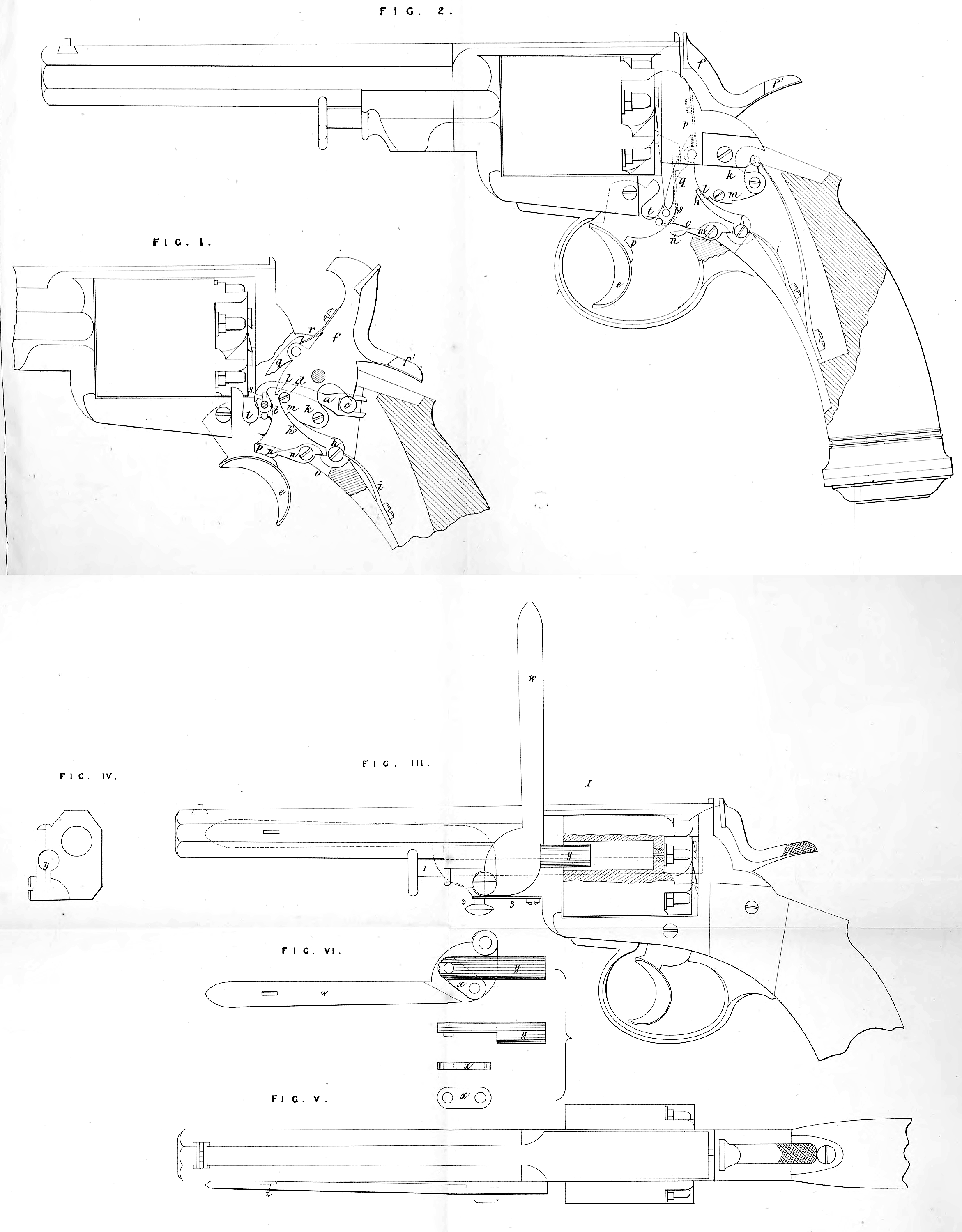
My Invention consists, firstly, of the method herein-after explained and illustrated in the accompanying Drawing of constructing the locks of repeating or revolving fire-arms, the hammers of the said locks being capable of being cocked either by the hand or by the trigger, and when the cocking is effected by the hand, the trigger is depressed to nearly the full extent of its range of motion.
Figure 1 of the accompanying Drawing illustrates this part of my Invention in elevation. In the said Figure 1, I have omitted several parts of the fire-arm which are not essentially connected with the mechanism which constitutes this part of my Invention, which said mechanism has for its object the depression of the trigger by the cocking of the hammer, a is a lever jointed to the trigger at b. The forked end of the lever a engages with the pin c, upon which it is capable of a sliding motion. A pin d screwed in the cock in the position represented, engages under the lever a. When the cock is raised by the thumb the pin d lifts the lever a, the said lever drawing back the trigger e, which assumes the position represented when the cock or hammer is at full cock.
My Invention consists, secondly, in the following method of holding the hammers or cocks of repeating or revolving fire-arms, and liberating the cocked hammers on discharging the fire-arms:—This part of my Invention is illustrated in Figures 1 and 2 of the accompanying Drawings, the parts being represented in Figure 1 in the positions which they occupy when the hammer is in full cock, and in Figure 2 in the positions which they occupy after the discharge of the fire-arm. The hammer or cock/ may be raised either by the action of the thumb upon the comb fl of the cock, or by the action of the finger upon the trigger e, as herein-after explained. A bent lever h somewhat resembling a bell-crank lever is pressed by a spring i so as to make its long arm h1 bear against the tumbler k of the cock, and as the cock is raised the said arm h1 engages in one or other of the two bents l, m> in the tumbler of the cock /. When the arm h1 of the lever h is engaged in either of the bents l, m, the cock is held at half-cock and full-cock respectively. The lever h is disengaged from the bents l, m, on the tumbler k, and the fire-arm discharged in the following manner:—A nearly straight lever n bears at its short end upon the short end of the cranked lever h. The long arm n1 of the lever n projects to a short distance through a hole in the under side of the lock case 0. When the trigger e is pressed by the finger, the part p of the trigger comes in contact with the projecting arm nl of the lever n9 and raising the said arm depresses the arm h1 of the cranked lever h, and disengages it from the bent in the tumbler in which it had been engaged. The cock / falls by the action of its spring, and the fire-arm is discharged. The cock may be raised by the action of the finger upon the trigger e instead of by pressing back the comb/1 of the cock. The trigger e effects the raising of the cock in the following manner:—An arm or lever q is jointed to the cock as represented, and pressed upon by the spring r. The lower end of the lever q engages in the notch s in the trigger e when the trigger is not pressed upon, and the hammer is not cocked. On pressing upon the trigger e the pressure is transmitted through the lever q to the cock /, and the cock is raised. When, however, the trigger e has been pressed nearly to the full extent of its range of motion, the lever q escapes from the notch s, the said lever falling into the space t of the trigger e, and the hammer falls. The revolving chamber is operated upon by a driver of the ordinary construction. Many of the other parts of the fire-arm represented in the Drawing are also of the ordinary construction, and I therefore do not think it necessary to describe the said parts.
My Invention consists, thirdly, in a loading rod for repeating or revolving fire-arms constructed in the manner represented in Figures 3, 4, 5, and 6 of the accompanying Drawings ; Figure 3 representing a side elevation of a repeating or revolving fire-arm having a loading rod constructed according to my Invention; Figure 4 a transverse vertical section of the same; Figure 5 a plan of the same; and Figure 6, separate parts of the loading rod and mechanism connected therewith.
A lever w is connected by a joint to the frame of the fire-arm. The said lever w is also connected by a link x to the loading rod y% which said loading rod slides in a nearly semicylindrical channel in the frame of the fire-arm. By moving the lever from the position shown in dotted lines in Figure 3 to the position w9 Figure 3, the loading rod y may be forced into the barrels of the revolving chamber.
The lever w engages with a catch z on the barrel of the fire-arm when it is not in use and is held in its place by the said catch.
My Invention consists, lastly, in fixing the axis of the revolving chamber of repeating or revolving fire-arms by means of a spring catch fastening placed underneath the fore part of the body of the fire-arm. This part of my Invention is illustrated in Figure 3 of the accompanying Drawings; 1 is the axis of the revolving chamber; 2 is a bolt pressed upwards by the spring 3. The upper end of the bolt 2 engages in a depression in the axis 1 and prevents the said axis from being withdrawn.
By pulling down the bolt 2 the said bolt is disengaged from the axis 1, and the said axis may be withdrawn.
Having now described the nature of my Invention, and the manner of carrying the same into effect, I wish it to be understood, that I do not limit myself to the precise details herein described, and illustrated in the accompanying Drawings, as the same may be varied without departing from the nature of my said Invention; but I claim as my Invention,—
Firstly, the arrangement of parts herein-before described and illustrated in the accompanying Drawings, whereby, when the hammer is cocked by pressure upon the comb of the cock, the trigger is drawn back nearly to the point to which it requires to be brought to discharge the fire-arm.
Secondly, the arrangement of parts herein-before described and illustrated in the accompanying Drawings, whereby the hammer is held in cock and the trigger is made to disengage the cocked hammer, and discharge the fire-arm.
Thirdly, the arrangement of parts herein-before described and illustrated in the accompanying Drawings, for actuating the loading rods of repeating or revolving fire-arms.
Lastly, fixing the axis of the revolving chamber of repeating or revolving fire-arms by a spring catch fastening as herein-before described and illustrated in the accompanying Drawings.
In witness whereof, I, the said Charles Reeves, have hereunto set my hand and seal, this Twenty-second day of June, in the year of our Lord One thousand eight hundred and fifty-eight.
CHARLES REEVES, (l.s.)
Witness,
Richard Skerrett,
Clerk to George Shaw.