
British 2625
LETTERS PATENT to John Field Swinburn, of Birmingham, in the County of Warwick, Gun Maker, for the Invention of “Improvements in Firearms.” —A communication from Thomas Bailey, of New Orleans, United States, Gun Maker.
Sealed the 13th April 1858, and dated the 14th October 1857.
PROVISIONAL SPECIFICATION left by the said John Field Swinbum at the Office of the Commissioners of Patents, with his Petition, on the 14th October 1857.
I, John Field Swinburn, of Birmingham, in the County of Warwick, Gun Maker, do hereby declare the nature of the said Invention for “Improvements in Fire-arms,” (being a communication from Thomas Bailey, of New Orleans, United States, Gun Maker,) to be as follows:—
This Invention consists in the mode herein-after described of constructing the locks of fire-arms so as to facilitate the action of the mainspring on the tumbler, and increase the readiness of the discharge of the tumbler, and with it the cock or hammer. For this purpose the arm of the tumbler and the swivel are so constructed and arranged on the lock, that the three points consisting of the centre or pivot of the tumbler, the connecting pin of the tumbler arm and swivel, and that of the latter with the end of the mainspring, shall be equidistant, and a line through the centre of the tumbler arm shall form an angle of about twenty-five degrees (or thereabouts) with and below a horizontal line through the centre or pivot of the tumbler when the lock is at rest; also when the tumbler is raised to “cock,” the tumbler arm will have moved through an arc of about fifty-eight degrees, or thereabouts, so as to form an angle of about thirty-three degrees, or thereabouts, with and above the said horizontal line, thereby causing the mainspring to pull light or easy at “cock” from the acuteness of the angle formed between the tumbler arm and the swivel at such time. The stud of the mainspring should be placed upon the extreme end of the turn, or upon the long or swivel side of the same, and is so placed on the plate of the lock as that the stud will form the true centre of the circle, the segment of which is described by the end of the swivel on the tumbler being raised from a position of rest into “cock.”
SPECIFICATION in pursuance of the conditions of the Letters Patent, filed by the said John Field Swinburn in the Great Seal Patent Office on the 14th April 1858.
TO ALL TO WHOM THESE PRESENTS SHALL COME, I, John Field Swinburn, of Birmingham, in the County of Warwick, Gun Maker, send greeting.
WHEREAS Her most Excellent Majesty Queen Victoria, by Her Letters Patent, bearing date the Fourteenth day of October, in the year of our Lord One thousand eight hundred and fifty-seven, in the twenty-first year of Her reign, did, for Herself, Her heirs and successors, give and grant unto me, the said John Field Swinburn, Her special license that I, the said John Field Swinburn, my executors, administrators, and assigns, or such others as I, the said John Field Swinburn, my executors, administrators, and assigns, should at any time agree with, and no others, from time to time and at all times there.after during the term therein expressed, should and lawfully might make, use, exercise, and vend, within the United Kingdom of Great Britain and Ireland, the Channel Islands, and Isle of Man, an Invention for “Improvements in Fire-arms,” being a communication from Thomas Bailey, of New Orleans, United States, Gun Maker, upon the condition (amongst others) that I, the said John Field Swinburn, by an instrument in writing under my hand and seal, should particularly describe and ascertain the nature of the said Invention, and in what manner the same was to be performed, and cause the same to be filed in the Great Seal Patent Office within six calendar months next and immediately after the date of the said Letters Patent.
NOW KNOW YE, that I, the said John Field Swinburn, do hereby declare the nature of the said Invention, and in what manner the same is to be performed, to be particularly described and ascertained in and by the following statement, reference being had to the Drawings hereunto annexed, and to the letters and figures marked thereon (that is to say):—
This Invention of “Improvements in Fire-arms” consists in the mode herein-after described of constructing the locks of fire-arms so as to facilitate the action of the mainspring on the tumbler, and increase the readiness of the discharge of the tumbler, and with it the cock or hammer. For this purpose the arm of the tumbler and the swivel are so constructed and arranged on the lock, that the three points consisting of the centre or pivot of the tumbler, the connecting pin of the tumbler arm and swivel, and that of the latter with the end of the mainspring, shall be equidistant, and a line through the centre of the tumbler arm shall form an angle of about twenty-five degrees, or thereabouts, with and below (for a front action lock, but for a back action or pistol lock above,) a horizontal line through the centre or pivot of the tumbler when the lock is at rest; also when the tumbler is raised to “cock,” the tumbler arm will have moved through an arc of about fifty-eight degrees, or thereabouts, so as to form an angle of about thirty-three degrees, or thereabouts with and above (for a front action lock, but for a back action or pistol lock below,) the said horizontal line, thereby causing the mainspring to pull light or easy at “cock” from the acuteness of the angle formed between the tumbler arm and the swivel at such time. The stud of the mainspring should be placed upon the extreme end of the turn, or upon the long or swivel side of the same, and is so placed on the plate of the lock, as that the stud will form the true centre of the circle, the segment of which is described by the end of the swivel on the tumbler being raised from a position of rest into “cock.”
Such being the nature of the Invention, I will proceed to describe more particularly the mode of carrying it into effect, by reference to the accompanying Drawings, in which are represented a front action lock and a back action lock, and a pistol lock with the working parts in the two positions above referred to.
Description op the Drawings.
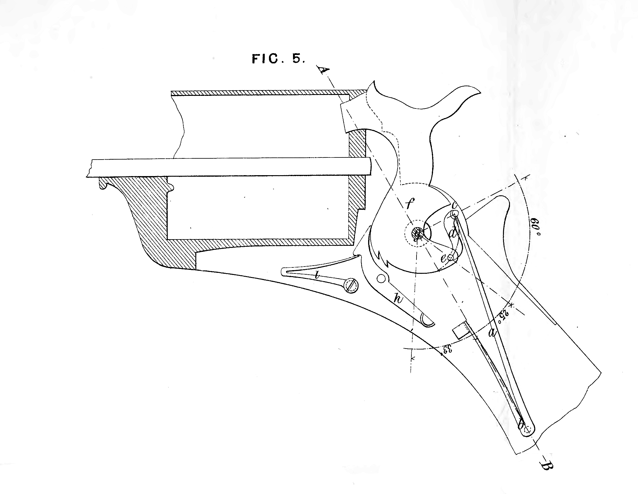
Fig. 1 is a side view of a front action lock with the working parts shewn at rest, the front plate being removed in order to exhibit the tumbler Fig. 2 is a similar view of the same with the working parts shewn at “ cock Figures 3 and 4 are corresponding views of a back action lock; Fig. 5 represents a pistol lock with the working parts at rest. In all these several Figures the same letters of reference indicate corresponding parts.
a is the mainspring; 5 is its stud or pivot; a is the swivel horn or point of connection between the end of the mainspring and the swivel; d is the swivel; e is the connecting pin of the swivel with the tumbler arm; / is the tumbler, with the usual bents or notches for the sear to pass into and press against the tumbler as required; g is the pivot or centre of motion of the tumbler; h is the sear intended to be acted upon as usual by the trigger; i is the ordinary sear spring. The mainspring is shewn detached in elevation at Fig. 6, and the tumbler with the swivel in side view at Fig. 7. On reference to Figures 1 and 3, it will be seen that when the working parts of the lock are at rest, the three points indicated by the letters c, e, g, are equidistant, and that a line through g, e, will form an angle of twenty-five degrees, or thereabouts, in the one case below, and in the other case above, a horizontal line A, B, drawn through the centre g of the tumbler pivot. It will also be seen, on reference to Figures 2 and 4, that when the working parts of the lock are “ at cock,” the connecting pin e will have passed from the point, at which with the point g it made an angle of twenty-five degrees, or thereabouts, with the horizontal line A, B, on one side of this line, and have arrived at a point at which g> ey will form an angle of thirty-three degrees, or thereabouts, on the other side of the line A, B ; thus the connecting pin e will have moved through an arc of fifty-eight degrees, or thereabouts, in passing from rest to “full cock,” and the angle formed by the swivel and the tumbler arm will have become much more acute, as may be seen by comparing the positions of these parts in Figures 1 and 3 with the same in Figures 2 and 4. It will also be seen that the stud b of the mainspring is fixed on the lock plate, in such a position as to form the centre of the circle, the arc or segment of which is described by the motion of the swivel horn c, from the position shewn in Figures 1 and 3 to that shewn in Figures 2 and 4.
By the foregoing arrangement of the parts it will be understood that the action of the mainspring on the tumbler for throwing the hammer on to the nipple will be easy when first the sear leaves the notch of the tumbler, but will increase in force and rapidity until the hammer is down on the nipple.
Having thus described the nature of the Invention communicated to me as aforesaid, and in what manner the same is to be performed, I would have it understood that what I claim is, the construction of the locks of fire-arms on the principle described, that is to say, so that the swivel horn c, the connecting pin e9 and the tumbler pivot g, may be equidistant, and the connecting pin e may be at an angle of about twenty-five degrees with the base line A, B, on one side when at rest, and move in an arc so far as to be at an angle of about thirty-three degrees with the same line on the other side of it when at “full cock,” also that the stud of the mainspring may be fixed to the lock plate in the position represented and described.
In witness whereof, I, the said John Field Swinburn, have hereunto set my hand and seal, the Thirteenth day of April, in the year of our Lord One thousand eight hundred and fifty-eight.
JOHN FIELD SWINBURN. (l.s.)
Witness,
William Spence,
50, Chancery Lane,