
US 36505
UNITED STATES PATENT OFFICE.
C. C, BRAND, OF.NORWICH,CONNEOTIOUT.
IMPROVEMENT IN REVOLVING FIRE-ARMS.
specification forming part of Letters Patent No. 36,505, dated September 23, S62.
To all whom it may concern:
Beit known that I, Christopher C. Brand, of Norwich, in the county of New London and State of Connecticut, have invented certain new and useful Improvements in Repeating Fire-Arms; and I do hereby declare that the following is a full clear, and exact description of my invention, reference being had to the accompanying drawings, in which—
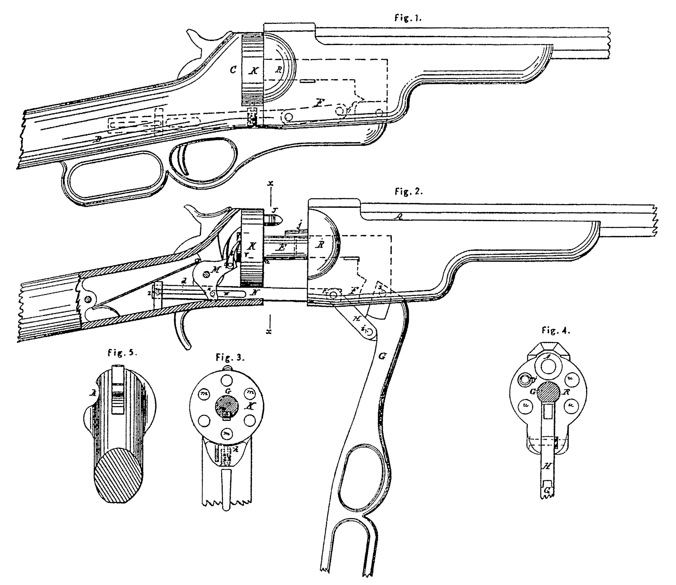
Figure 1 represents a side view of certain parts of a repeating-rifle embodying my improvements. Fig. 2 represents a side view of the same with the breech open and certain parts removed to show the interior construction. Fig. 3 represents a transverse section of the same at the line x x of Fig.2 and looking towards the cylinder. Fig. 4 represents a transverse section of the same, looking toward the barrel, and Fig. 5 represents a rear view of a portion of the stock, looking forward.
My invention relates to that class of repeating fire-arms which are adapted to the use of metallic cartridges that are inserted into the revolving cylinder at its butt; and my invention embraces several parts, which are not necessarily used in connection. As, however, I believe the pest fire-arms can be constructed by the simultaneous use of all parts of my invention, I shall proceed to describe one in which they are all embodied.
Tie object of the first part of my invention is to prevent the escape of smoke and lead at the joint between. the revolving cylinder and the butt of the barrel. To this end the first part of my invention consists in making the length of the revolving cylinder shorter than the length of the cartridge-case, so that the front end of a cartridge, when in a chamber of the cylinder, protrudes in front of it, and in combining the said cylinder with the barrel by means of mechanism in such manner that the cylinder is withdrawn from the butt of the barrel prior to its rotation sufficiently to permit the end of the cartridge to turn, and is moved toward the barrel to close the breech and insert the protruding end of the cartridge into the butt of the barrel. By this combination the front end of the cartridge-case is caused to overlap the joint of the breech at the time the charge is fired to prevent the escape thereat of any matter from within.
The object of the second part of my invention is to protect the front ends of the cartridge, which protrude beyond the front end of the revolving cylinder. This part of my invention consists in combining a short revolving cylinder to hold the cartridges with a casing in advance of said short cylinder to receive their projecting ends and protect them from injury.
The object of the third part of my invention is to relieve the hammer from the strain of revolving the cylinder, which is the customary arrangement in this class of fire-arms. To this end this part of tiny invention consists in combining the lever which moves a sliding revolving cylinder with the mechanism for operating the revolution of the said cylinder, so that the said lever performs the two functions of moving the cylinder to and fro in line with the barrel and also of revolving it.
The object of the fourth part of my invention is to loosen the discharged-cartridge cases from the cylinder without removing the same from its place. This part of my invention consists in combining the lever which proves a sliding revolving cylinder to and fro with a punch so located as to enter the discharged-cartridge case when the cylinder is moved forward, and sufficiently long to loosen said case from its chamber.
The fifth part of my invention consists in constricting the said punch in such manner and so combining it with the other members of the fire-arm that it performs the double function of loosening the cartridge-case and of preventing the rotation of the revolving cylinder during firing.
The fire-arm represented in the accompanying drawings is divided into two main divisions, which are combined by means of a sliding bolt, E, and toggle-joined lever G. The revolving cylinder K, which receives the cartridges, is pivoted on the sliding bolt E, which thus forms the spindle on which the cylinder revolves. It is pierced in this instance with six chambers, m for cartridges, and it is so short that the front ends of the cartridge-cases protrude beyond its front end, as shown at J, Fig. 2, when the cartridges are in place, The lever is pivoted at its fulcrum to the front end of a link, H, which in turn is pivoted to the part of the stock F to which the barrel A is secured. The front end of the lever is pivoted to the front end of the sliding bolt, and the dimensions of the parts are such that when the lever is depressed, as shown in Fig. 2, the revolving cylinder, the main portion of the stock, and the appurtenances thereof are moved back from the butt of the barrel, leaving ample space between the front end of the cylinder and tie barrel for the projecting ends of the cartridges to turn into line with the barrel without striking. The cylinder is retained in its place on the spindle by a spring-catch a. The lever G in this instance is so formed and arranged that it forms the trigger-guard, and its after end, which is in the for in of a flattened ring, is in a convenient position to be clutched by the fingers of the hand which grasps the handle D of the stock at to time the trigger is drawn. In order that the force of the discharge may not tend to depress the lever G, the connections are constructed in such manner that the central joint pin, i, is above the line connecting the other two joint-pins, r s, when the lever is raised to its place in contact with the stock.
In order that the front ends of the cartridges that project from the cylinder may not be injured, a casing, R, is secured to that part of the stock which is beneath the barrel to receive the ends of the cartridges when the breech is closed by the forward movement of the cylinder. In the present example the case is formed of a block perforated with holes u, corresponding in position with tile clambers of the cylinder when the latter is in place against the butt of the barrel; but lie casing may be a mere shell of sufficient strength, audit may be open at its front end, if deemed expedient.
In order to revolve the cylinder according to the third part of my invention the butt of the cylinder is fitted with a ratchet-wheel, v, whose teeth are operated upon by a spring-pawl, l, which is pivoted to one arm of a vibrating pawl-lever, M, having the form of a bell-crank. The lower arm of this pawl-lever is fitted with a pin, x, which is received in a slot, w, in a bar, N, whose front end is made fast to the front division of the fire-arm. The hinder end of the slotted bar slides in the hinder division of the fire-arm. The slot is extended backward to such a point that during the backward movement of the cylinder K and its appurtenances by the depression of the lever G the hinder end of the slot comes in contact with the pin x of the vibrating pawl-lever before the cylinder reaches its most backward position, so that the continued movement of the cylinder is the lever G causes the pawl-lever to vibrate on its pivot and rotate the cylinder. This rotation of the cylinder continues until the chamber previously in line with the barrel is moved past it and a succeeding chamber is brought into line with the barrel. When this is accomplished the further rotation of the cylinder and its further movement backward by the ever G are simultaneously stopped by a stop-pin, z, which comes in contact with the hinder end of a supplementary slot, d, in the slotted bar N. The front end of the slot to is in such a position that, when the cylinder K is moved forward by the lever G the pin x of the pawl-lever comes in contact with the front end of the slot sufficiently before the cylinder reaches its place at the butt of the barrel to move the pawl lever the distance required to withdraw the pawl from the ratchet-tooth with which it was in contact and engage it with the tooth appertaining to the succeeding chamber of the cylinder. In order to prevent the cylinder from turning by momentum after the lever G is at rest, a spring-stud, i, is provided. This stud is borne against the periphery of the cylinder by a spiral spring, and acts as a friction-brake to prevent the over movement of the cylinder.
The cartridge-cases are so completely contained in the chambers that they require to be punched back after firing. In order to effect this without requiring an additional movement of the band, a punch,j, is secured to the casing-block R in such position that it enter the last discharge-cartridge case as the cylinder is moved forward by the lever G to place a succeeding cartridge for firing. The punch projects sufficiently from its attachment to strike the inner site of the butt of the cartridge-case before the cylinder reaches its place at the butt of the barrel, and a notch, k, is formed in the recoil-shield behind the punch to permit the cartridge-case to move back when struck by the punch. By this arrangement of the punch the loosening of the discharged-cartridge case is effected by the operation of the same lever, G, which moves the cylinder, and no additional lever is required for the purpose. In order that the punch may also lock the cylinder from revolving when it is moved it to place at the butt of the barrel, the base of the punch is made to fit the bore of the chambers, so that it engages with the one it enters like a bolt.
The fire-arm thus described is constructed to ignite the powder by means of percussion-printers contained in the butt of the cartridge, and the hammer is fitted with a nose, which strikes the butt of the cartridge through a hole made in the recoil-shield G. It is readily charged when the cylinder has been moved back by inserting the cartridges successively in the butts of the chambers as they are brought in succession opposite the notch k in the recoil-shield by turning the cylinder by hand. As the punch i occupies the place of a cartridge when the cylinder is at the butt of the barrel, the chamber corresponding thereto cannot be charged when the fire-arm is fitted with the punch arranged as described.
Having thus described a repeating fire-arm embodying all parts of my invention what I claim as new, and desire to secure by Letters Patent, is—
1. The combination of a cylinder shorter than the cartridges with the barrel by mechanism in such manner that the cylinder is drawn from the butt of the barrel prior to its rotation, and is moved toward tie barrel to insert the front end of the cartridge therein prior to firing, substantially as set forth.
2. The combination of a cylinder shorter than the cartridges with a stationary casing to protect their protruding front ends, substantially as set forth.
3. The combination of a turning-cylinder with a lever by mechanism in such manner that the said cylinder is both turned and moved toward and from the butt of the barrel by the said lever, substantially as set forth.
4. The combination of a discharge-punch with the lever for moving the cylinder toward and from the butt of the barrel, so that the cartridge-case is loosened from the chamber by the working of said lever, substantially as set forth.
5. The construction and combination of the discharge-punch with the other members of the fire-arm in such manner that said punch performs the double function of discharging the cartridge-cases and of locking the cylinder in its proper position, substantially as set forth.
In testimony whereof I have hereunto subscribed my name.
CHRISTOPHER, C. BRAND.
Witnesses:
Wm. S. Brewer,
S. T. Holbrook.