
US 35996
UNITED STATES PATENT OFFICE.
JAMES B. DOOLITTLE, OF SEYMOUR, CONNECTICUT.
IMPROVEMENT IN MAGAZINE FIRE-ARMS.
Specification forming part of Letters Patent No. 35,996, dated July 29, 1862.
To all whom it may concern:
Be it known that I, James B. Doolittle, of Seymour, in the county of New Haven and State of Connecticut, have invented a new and useful Improvement in Repeating Fire-Arms; and I do hereby declare that the following is a full, clear, and exact description of the same, reference being had to the accompanying drawings, forming part of this specification, in which—
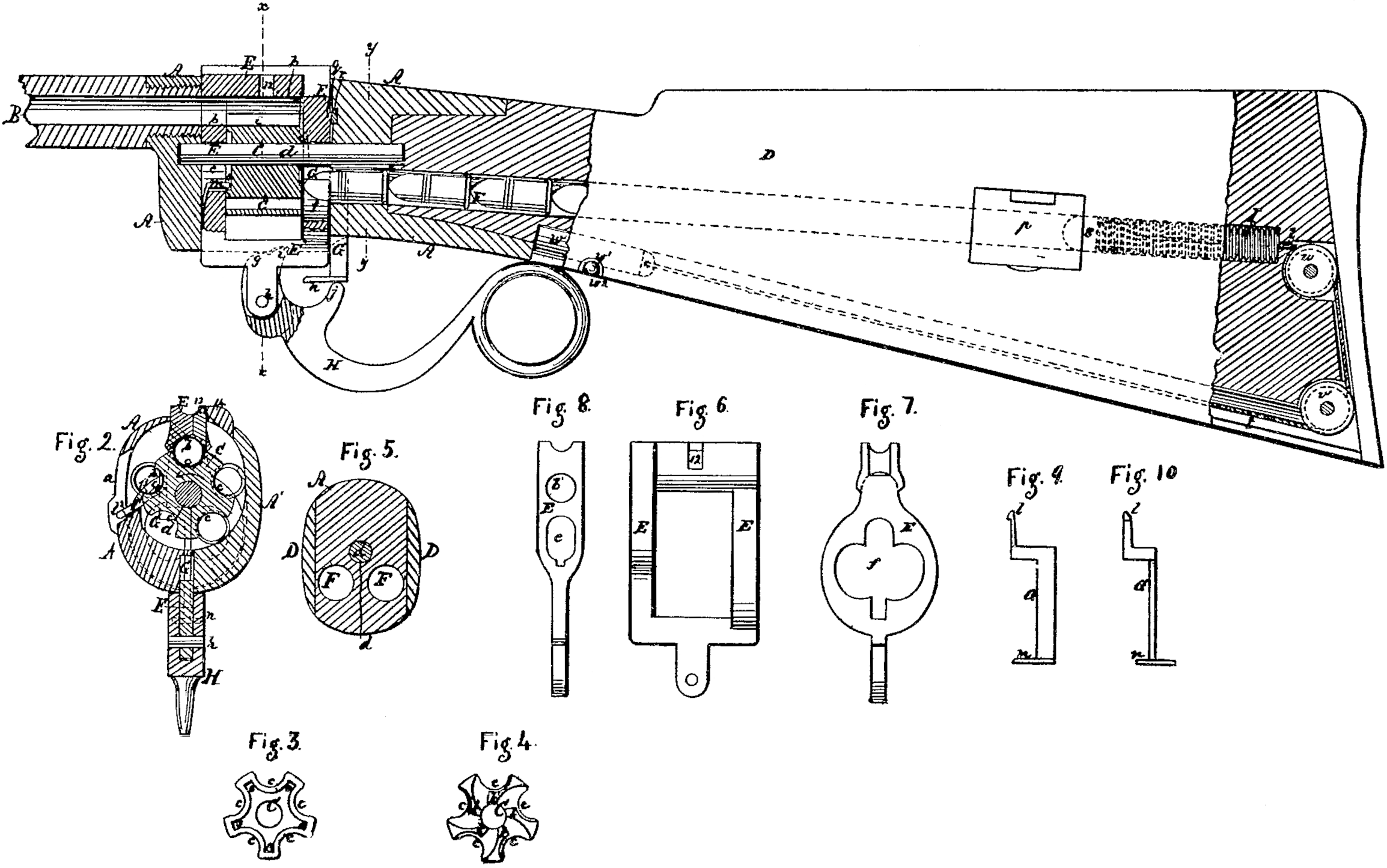
Figure 1 is a central longitudinal vertical section of a repeating-rifle with my improvements, omitting all of the barrel that is not necessary to illustrate the invention. Fig. 2 is a transverse section of the same in the plane indicated by the line x x of Fig. 1. Fig. 3 is a front view of the rotating cylinder. Fig. 4 is a back view of the same. Fig. 5 is a transverse section of the stock in the plane indicated by the line y y, Fig. 1. Fig. 6 is a side view of the cylinder-yoke. Fig. 7 is a back view of the same. Fig. 8 is a front view of the same. Fig. 9 is a side view of the dog by which the rotation of the cylinder is effected. Fig. 10 is a front view of the same.
Similar letters of reference indicate corresponding parts in the several figures.
This invention consists, mainly, in a certain construction of and mode of operating a series of chambers by which cartridges are received from one or more magazines in the stock of the fire-arm and conveyed to a point opposite the barrel to be fed.
To enable others skilled in the art to make and use my invention, I will proceed to describe its construction and operation.
A is the frame, of steel or iron, which attaches the barrel B to the stock D, and which contains the rotating cylinder and sliding yoke E. The general form of the frame A is substantially like that of fire-arms commonly constructed with the rotating many-chambered cylinder, except that, instead of being entirely open on both sides, it has a comparatively small opening, a, on the right side, (shown at the left of Fig. 4, which is taken looking in a forward-direction,) and has its other side closed by a plate, A’, which is screwed on after the cylinder C and yoke have been put in. The said frame is slotted vertically the whole length of its interior for the reception of the sliding yoke E, which works vertically right through the top and bottom of it.
The yoke E has a quadrangular opening in a lateral direction, said opening being just long enough from back to front to receive the cylinder lengthwise within it without interfering with its own upward and downward movement in the frame A, or with the rotation of the cylinder, and its depth from top to bottom is sufficient to permit it to work up and down some distance independently of the cylinder.
The cylinder C is not chambered like that of an ordinary revolver, but only what may be termed “half-chambered,” having in its periphery, a number of semi-cylindrical cavities, cc, parallel with and at equal distances from its axis and at equal distances from each other, each of these cavities constituting one half of a chamber from which the charge is to be fired, and a semi-cylindrical cavity, b, in the interior of the upper part of the yoke E being made to combine with either of the cavities c c, and with each in turn to form the complete chamber, the yoke and the cylinder being so fitted as to be capable of forming gastight joints at the sides of the chambers. The cylinder has simply a rotary motion on the fixed axis-pin d, which is secured in the frame A.
The yoke E has an upward and downward movement, the downward movement serving to bring the part b of the chambers into connection with the parts co preparatory to firing, and the upward movement being for the removal of the part b to permit the cylinder to rotate, such upward movement being sufficient to allow the discharged shells to clear the upper part of the yoke that they may be conveyed by the rotation of the cylinder to the opening, a provided in the frame A for their discharge. In the front of the yoke there is a circular opening, b’, corresponding with the bore of the barrel and concentric with the cavity b, and below this there is an elongated hole, e, for the passage of the base-pin d. In the back part of the yoke there is an opening, f f, the form of which is shown in Fig. 1, said opening being made very wide to permit of the passage of cartridges from either of the two magazines FF, which are arranged side by side within and lengthwise of the stock, into the half-chambers c c of the cylinder.
The said opening is also deep enough to permit the passage of the base-pin through its upper part, and to permit the dog G, through which the rotation of the cylinder is effected, to Work through its lower part. The upper part of the back of the yoke, in rear of and below the cavity b, constitutes the breech, and on the back surface of this part of the yoke there is formed an inclined plane, q, to operate against a reversed inclined plane, r, provided in the back part of the frame A, as shown in Fig. 1. By means of these inclined planes the yoke is forced forward against the barrel as it is brought down upon the cylinder.
The inclined plane r is made of a separate piece of steel slipped into a groove of dovetail form provided in the back of the frame A for its reception. In the top part of the yoke, in the side farthest from the opening a in the frame, there is fitted into a mortise, 12, a vertically-sliding tooth, 13, which is capable of entering the cavity b, and above this tooth there is provided on the top of the frame A a fixed tooth, 14, by which, when the yoke is moved upward to open a chamber, e b, the said tooth 13 is prevented from rising all the way with the yoke, and so caused to press down the cartridge-shells which have been discharged, and detach them from the yoke in case of their sticking to it, so that they may be carried round by the cylinder to be thrown out at the opening a. When the yoke is brought down again upon a cartridge in one of the half-chambers c c, the tooth 13, on striking the cartridge, has its further descent stopped, while the yoke completes its descent.
Behind the cylinder a small hook, l, is arranged to work in the opening a of the frame A, for the purpose of tripping out the shells from the half-chambers c c in case of their having any tendency to stick therein. This hook has a slight swinging movement from a pivot,l^2 , which attaches it to the frame A, and is operated by means of the yoke E, in the back of whose interior there is a groove for the reception of the said hook.
His a lever, by which the operations of the yoke E and cylinder C to effect the repeated loading from the magazine are produced. This lever is arranged under the stock to serve as a trigger-guard, and is pivoted by a pin, h, to the bottom of the yoke, and has formed upon it a cam-like surface, g, and two horns, i j, the surface g being intended to act as a cam against the bottom of the frame A for the purpose of drawing down and closing the yoke, the horn i being for the purpose of drawing down the dog G against the teeth k k on the back of the cylinder, and thereby producing the rotation thereof, and the horn j being for … the purpose of forcing up the said dog to enable it to pass over the said teeth. The dog G is fitted to slide vertically in a guide in the back of the frame A immediately behind the yoke, and its upper part works through the opening in the back of the yoke on the right hand side of the axis-pin d. The upper portion of the said dog below the tooth or hook is elastic, to enable said tooth or hook to spring back and pass over the teeth k k in the upward movement of the dog. The lower part of the dog protrudes through the bottom of the frame A, and at its lower extremity there is formed a tooth-like forward projection, n, for the horns i j to act upon to produce its operation. In front of the yoke there is secured a locking-pin, m, which engages in a series of radiating notches, o o, in a cavity in the front of the cylinder, for the purpose of locking the cylinder after any one of the half-chambers c c has been brought opposite to the chamber b by the act of bringing down the yoke to complete the chamber.
The two magazines F provided in the stock are arranged on opposite sides of a plane passing vertically and centrally through the stock and the axis-pin d and with their mouths, which are in the frame A, below the axis-pin d, at a distance apart corresponding with the distance between the half-chambers c c, by which arrangement, and by providing a proper number of half-chambers c c in the cylinder, there is always a half-chamber opposite each magazine whenever a chamber is opposite to the barrel. The said magazines are filled with cartridges through small doors p p, provided on the sides of the stock, and the cartridges are fed forward within them and supplied to the cylinder by means of a spiral spring, I, and a follower, s, in each; and in order to enable the springs to be compressed and the followers to be drawn back beyond their respective doors p p, cords t are attached at one end to the followers and conducted round pulleys u, v, arranged within the back of the stock, and the other ends of the said cords are attached to a slide, w, working in a groove in the under side of the stock. This slide has a knob, w’, protruding through the groove to serve as a handle, and in the front portion of the groove there is on one side a notch, w^2, for the reception of this knob. By drawing forward the knob was far as the notch w^2, the followers s are drawn back beyond the doors p p, and by turning the said knob aside into the said notch the slide w and the followers are secured while the magazines are filled, and after both have been filled the knob w’ is turned aside from the notch w^2, and the springs are allowed to press the cartridges forward toward the cylinder.
The rotation of the cylinder is in such a direction (indicated by an arrow in Fig. 2) that each half-chamber c arrives first opposite the magazine on the right-hand side of the stock, and then opposite that on the left-hand side, and hence while there are cartridges in the right-hand magazine the half-chambers c c, as they severally arrive opposite to that magazine, each receive a cartridge therefrom, and being occupied as they pass the left-hand magazine cannot, receive any therefrom; but, as after all the cartridges have been delivered from the right-hand magazine the half-chambers arrive empty at the left-hand one, and each receives a cartridge from the latter. Thus it will be understood that first all the cartridges in the right-hand magazine and afterward all those in the left-hand magazine are used. The cartridges are confined in the half-chambers c c as the latter move toward a position opposite the barrel by the circular form of the interior of the bottom of the frame A and of the interior of the plate A’.
The construction and movements of the several parts of the arm having now been described, I will proceed to describe as briefly as I can the operations of loading and firing, first remarking that the lock, which is not represented in the drawing, may be of ordinary, construction. When the gun is in condition for firing, as shown in Figs. 1 and 2, the lever H lies back close under the stock, and its cam-like portion g is bearing against the bottom of the frame A in such a manner as to hold down the yoke tight upon the cylinder. After firing, the lever H is pulled down from the position shown in Fig. 1 by taking hold of the ring at its rear end, and its horn i is brought into contact with the foot n of the dog G, and as the dog cannot descend to produce the rotation of the cylinder before the latter is left free to rotate by raising the yoke, the said foot becomes the fulcrum of the lever, which consequently raises the yoke as far as permitted by the frame A— viz., far enough to permit the rotating of the cylinder— and when the yoke can rise no further the pin h becomes the fulcrum of the lever, and the horn i, by its pressure on the foot n, depresses the dog H and produces the rotation of the cylinder, thereby causing it to carry away from opposite the barrel the cartridge-case which has just been discharged, and cause the said case to drop out laterally from the half-chamber c which has contained it, and through the opening a in the frame. The rotation of the cylinder also brings the next half-chamber containing a cartridge opposite to the barrel and within the yoke, and at the same time takes away from the magazine the half-chamber c, which has just received a cartridge therefrom, and brings another half-chamber opposite to the magazine for the reception of a cartridge. By drawing up the lever again to the position shown in Fig. 1, the horn j is brought into contact with the foot in of the dog (G, and the said dog is thereby moved upward to a position to engage with a new tooth, k, of the cylinder, and the yoke is drawn down to bring its half-chamber b into combination with the half-chamber c, which is opposite to the barrel, and everything is in condition for repeating the fire by drawing the trigger. In the operation of drawing down the yoke the bearing-point of the cam-like portion g of the lever becomes the fulcrum thereof, and hence it will be understood that the lever, in the several stages of its operation, has three distinct fulcrums, the other two being the pin h and the foot n of the dog, as before described. The cocking may be effected through the agency of the lever H, or by the independent action of the hammer.
What I claim as my invention, and desire to secure by Letters Patent, is—
1. The combination, in a fire-arm, in the manner substantially as herein described of a cylinder constructed with a series of half chambers, c c, and the sliding yoke E, constructed with a single half-chamber, b.
2. Combining the yoke E and the dog G, which produces the rotation of the cylinder, by means of a lever, H, applied substantially as herein specified, with its fulcrum variable, in the manner, set forth.
3. The combination of the sliding tooth 13 in the yoke and the fixed tooth 14 on the frame, substantially as and for the purpose herein specified.
4. The combination of the radial grooves or notches o o in the front end of the cylinder and the pin m, working through the front of the yoke, substantially as herein described, for the purpose of locking the cylinder.
5. The hook l’, applied within the opening a of the frame A, in combination with the cylinder C and operated by the yoke E, substantially as herein specified.
J. B. DOOLITTLE.
Witnesses:
H. C. Miles,
Lott Fenn.