
US 35999
UNITED STATES PATENT OFFICE.
GEORGE W. B. GEDNEY, OF NEW YORK, N.Y.
IMPROVEMENT IN REVOLVING FIRE-ARMS.
Specification forming part of Letters Patent No. 35,999, dated July 29, 1862.
To all whom it may concern:
Be it known that I, GEORGE W. B. GEDNEY, of the city, county, and State of New York, have invented certain new and useful Improvements in Fire-Arms; and I do hereby declare the following to be a full, clear, and exact description of the construction and operation of the sane, reference being had to the accompanying drawings, making a part of this specification, it which—
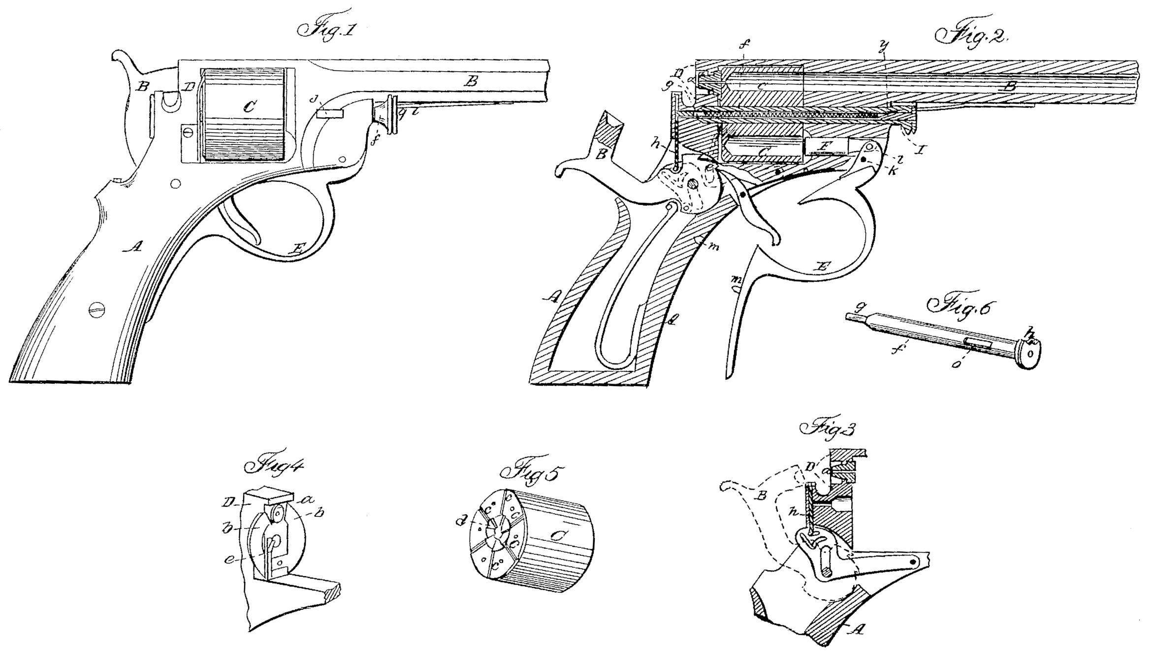
Figure 1 represents a side view of a pistol with a portion of the barrel broken away. Fig. 2 represents a longitudinal vertical section through the same, showing the interior. Fig. 3 represents a section through the rear of the pistol to show the priming arrangement, Figs. 4, 5, and 6 represent details of the fire-arm detached from the arm.
Similar letters of reference, where they occur in the different figures, denote like parts of the arm in all cases.
This invention embraces several distinct objects, all of which tend to make the fire-arm valuable and reliable, as well as simple, cheap, and efficient.
I enumerate my improvements as follows:
First. But one cone is used, and by making it with a broad ground joint base it has a greater bearing-surface, is less liable to break by the concussion of the hammer on its face, is more easily replaced in case it should break or become worn out, it obviates the necessity of making the cylinder one-third longer for cone-seats, and the cutting of them and a thread therein for as many cones as there are chambers, and by shortening the cylinder to a proper length for the charge it permits its weight to be brought more to the rear or butt of the pistol and over the hand, where the principal weight of it ought to be.
Second. In the use of circular compensating springs, which I fasten to the frame in rear of the cylinder, the ends or edges of which are turned at nearly right angles, for the purpose of breaking into or entering radiating grooves cut in the rear of the cylinder between and equidistant from the vent-holes, which controls the revolution of and retains the cylinder in position until revolved by the recocking of the hammer. These springs and grooves also prevent the escape of gas at the joint between the face of the cylinder and the barrel by a uniform pressure, also the possible ignition of the charge in the other chambers through the Vent, as sometimes occurs where caps are used.
Third. The making of the pin on which the cylinder revolves hollow, for the purpose of receiving and using a stick of water-proof-composition priming free from copper, by which twenty or more discharges of the chambers can be made with one primer, and which can be adjusted in less time than a cap for one discharge can be put on the cone, and when adjusted is not liable to drop out or miss fire, as is frequently the case with the best of caps. The primer is inserted in a slot in the stock frame forward of the cylinder, as will be hereinafter explained.
Fourth. In using the trigger-guard as a lever to ram home the charge inserted in the chambers when the bow of the guard becomes a spring to hold itself in position when acting as a guard alone.
Fifth. In cutting off the priming from a stick of priming material and carrying it up to the front of the hammer, so that the hammer will take and explode it against the nipple.
Sixth. In the use of a single spring on the under side of the barrel for keeping the plunger and cylinder-pin in place, and allowing the plunger to be withdrawn independent of the pin.
To enable others skilled in the art to make and use my invention, I Will proceed to describe the same with reference to the drawings.
A represents the stock, B the barrel, C the revolving cylinder, and B’ the hammer, of a pistol, these parts being made in any of the usual well-known ways, or of any ordinary material used for that purpose.
D represents a portion of the frame of the arm behind the cylinder. In this frame is placed a single cone, a, which serves to ignite all the charges as they come around opposite to it by means of the priming exploded against it by the hammer. The cone fits close up against the rear of the cylinder C, as seen in the drawings, and by removing the cylinder the cone can be slipped out of its seat at any time, it not being screwed in, as is usual in fire-arms, and being capable of moving only toward the cylinder, should the blow of the hammer start it, it would tend to close the joint more tightly between itself and the cylinder.
To the frame D, immediately behind the cylinder C, are connected two springs, b b, the ends of which are turned so as to take into radial grooves c, Fig. 5, cut in the rear of the cylinder. These springs perform several offices, as above stated, viz: They press the cylinder forward against the barrel; they scrape off the gas or gummy or dirty matter that accumulates on the cylinder; but especially they form a cut-off between the chamber that is to be exploded and the adjacent loaded one, and thus prevent the fire of the priming from igniting the adjacent or any other loaded chamber.
d, Fig.5, shows the ratchet by which the cylinder is evolved by means of a dog or pawl, e, (shown in red in Fig. 2,) in the usual way. There are no nipples in the cylinder, and hence it may be lighter and more cheaply made than when each chamber has its own nipple.
The pin f, upon which the cylinder C is revolved, is made hollow, so as to receive the priming which I use, and which is shown in red lines in Fig.2. Through the pin f is passed a plunger, g, which, by means of an inclosed spring, forces the priming up into proper position, where a cutter and carrier, h, that is actuated by the hammer B’, takes a slice or portion, and raising it up to the line or path of the hammer, which takes it and, carrying it against the nipple a, explodes it, and through the nipple and vent opposite to it explodes the charge.
i is a spring, which holds both the pin f and plunger g in place, the latter being susceptible of being withdrawn to insert a new stick priming without withdrawing the pin. The mode of inserting the priming is as follows: An opening, j, is made through the frame or casing of the arm, and, the plunger having been first drawn back, the priming is slipped into the hole j, and hence passes into the hollow of the pin f. The plunger is the run down, which carries the priming clear back into the chamber through which the cutter or carrier h passes, the coiled spring in the plunger keeping it fed up as the cutter or carrier takes it to the hammer.
The trigger-guard E is hinged at k, and upon its short arm l is pivoted the rammer F, for ramming home the charges. Upon this trigger-guard there is a projection, m, which takes into an opening, n, in the stock or casing, and the bow of the trigger-guard acts as a spring to hold itself firmly to the stock, but yet to be readily loosened when it is to be used as a rammer.
The cutter and carrier h is operated from the hammer B’, so as to move up and down through the shield or case, cutting off and carrying up a slice of the priming material at each up-and down movement of the hammer.
There are many details of the gun which it is deemed unnecessary to more particularly refer to, as they are clearly shown in the drawings— as, for instance, opposite the opening j in the frame there is a corresponding opening, o, in the pin f, through which the priming is to pass to the hollow of the pin, and the notch p of the pin, which fits the angles and sides of the barrel, always brings these openings opposite to each other.
What I claim is—
1. Setting the nipple loosely in the frame, and without connecting it permanently with any part of the arm, substantially as and for the purpose set forth.
2. The double circular springs in rear of the cylinder, made as described, and attached to the frame, as and for the purpose set forth.
3. Cutting of the priming at right angles with the position of the primer in the hollow cylinder-pin and carrying the same to the front of the hammer, to be caught by the cup of the hammer-face, under an arrangement of parts substantially such as set forth.
4. In combination with a hollow cylinder-pin for containing the priming, the openings j o, for the purpose of inserting the priming without withdrawing the cylinder-pin or plunger, substantially as described.
5. The spring or its equivalent on the under side of the barrel, for the purpose of keeping the cylinder-pin and plunger in place and allowing the latter to be withdrawn independent of the former, or both at once, substantially as set forth.
G. W. B. GEDNEY.
Witnesses:
Robert Taylor,
Edward G. Judson.