
Britain 659
A.D. 1865, 9th March. N ° 659.
LETTERS PATENT to William Clark, of 53, Chancery Lane, in the County of Middlesex, Engineer and Patent Agent, for the Invention of “Improvements In Revolving Fire-Arms.” — A communication from abroad by Sébastien Amédée Noël, ex Master at Arms, and François Gueury, Armourer, both of 29, Boulevart St. Martin, Paris.
Sealed the 25th August 1865, and dated the 9th March 1865.
PROVISIONAL SPECIFICATION left by the said William Clark at the Office of the Commissioners of Patents, with his Petition, on the 9th March 1865.
I, WILLIAM CLARK, of 53, Chancery Lane, in the County of Middlesex, 5 Engineer and Patent Agent, do hereby declare the nature of the said Invention for “IMPROVEMENTS IN REVOLVING FIRE-ARMS, to be as follows:—
This Invention relates to improvements in revolver pistols and other revolver fire- arms; the chief features consist—
1st. In the simplicity in the arrangement of the parts.
2ndly. In the position of the barrel relatively to the chamber containing the cartridges, the axis of the one being at right angles to the other, but in which the ball is forced to enter the barrel; this arrangement is of especial advantage in aiming.
3rdly. In the arrangement of a chamber for containing cartridges.
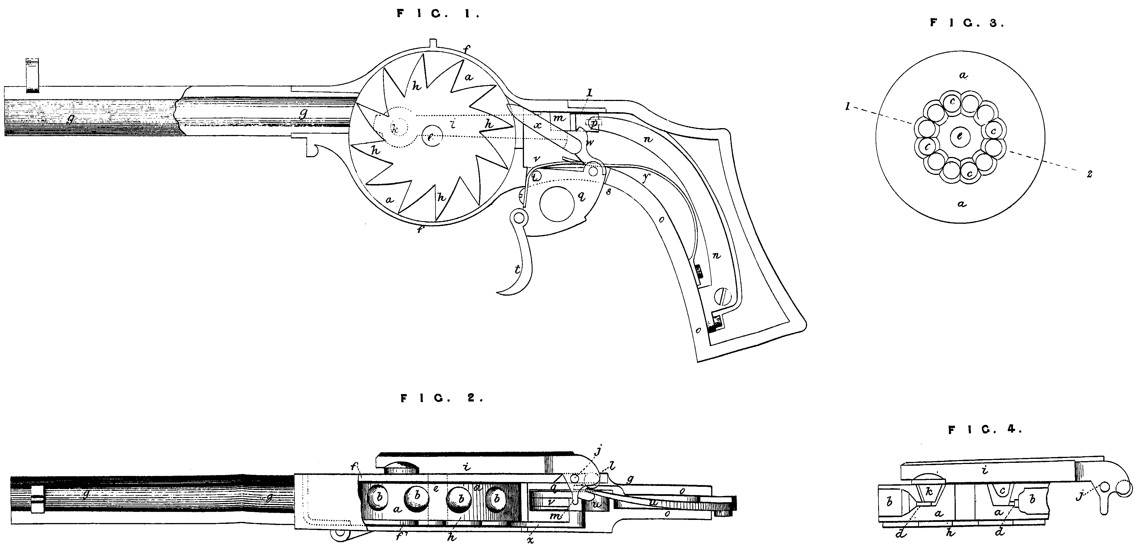
The Invention is illustrated in the accompanying Drawing; Fig. 1 of which shows a sectional elevation of a revolver; Fig. 2, a plan of same with stock removed; Fig. 3, an end view of the chamber containing the cartridges; and Fig. 4 a section of same on line 1, 2, Fig. 3. The letters apply to all 5 the Figures.
a, chamber of the revolver; b, b, cavities, a suitable number of which are made in its periphery for receiving the cartridges; C, c, cavities made in one side of chamber a, of the same number as b, b, and communicating there with by a small channel d, as seen in Fig. 4. The cartridges are placed in cavities b, and the caps of said cartridges are received in small channels d at the bottom of said cavities. The chamber a turns on an axis e, mounted in a hollow cylindrical part f of the same diameter forming the frame of the revolver, and closed by a plate f^1; g, barrel of the pistol as seen at Fig. 1; the axis of the breech chamber is at right angles to the axis of the barrel, and differing from the usual arrangement; h, ratchet wheel fixed on one side of chamber a, having a number of teeth equal to that of the cartridges, and serving to produce the rotation of the breech chamber by the mechanism herein-after described; i, lever acting as a hammer pivotted at one end on a screw ], the other end being furnished with a conical nose k of the same form as cavities ç, c, and penetrating therein successively in order to produce the ignition of the cartridges; l, m, lugs formed on the end of lever i, near its centre of oscillation; n, spring fixed to guard plate o, also forming part of the frame of the pistol; this spring bears on lug piece l, which is furnished with a friction roller p in order to keep the nose k of lever i firmly down on the cap; q, part oscillating at v in opening s; t, trigger piece regulating the position of part q; u, catch oscillating on part q and maintained in the raised position shown at Fig. 1 by means of spring v; y, spring fixed to plate o, and bearing on part q in order to keep it in the position seen at Fig. 1.
The parts being arranged as described, the following is the action of the pistol. If pressure be exerted on trigger t, the part q will oscillate on point r, catch u also participating in such movement, the latter by acting on lug m causes the lever i to turn on its axis j. In this movement the catch a causes the chamber a to turn one- twelfth of a revolution (supposing there are twelve cartridges), after which catch u is liberated from lug m, and lever i being released by the pressure exerted on part l by spring n causes the conical nose k to enter a cavity c with sufficient force to produce the ignition of the. cartridge. The part q is returned to position by spring y until lever i is again raised by exerting pressure on trigger t turning the chamber another twelfth of a revolution, to produce the discharge of the succeeding cartridge, and so on.
It will be readily understood that three or more chambers may be kept readily charged, it being simply necessary to remove plate f, and apply one ready charged on axis e after having removed the chamber that has been dis charged.
The Invention thus consists in the herein-described improvements in revolvers as distinguished—
1st. By the simplicity in the construction of the various parts, the wood butt being in one piece, as also the metal band forming the frame therefor.
2ndly. In the relative positions of the charge chamber and barrel, the one being mounted at right angles to the other.
And, 3rdly. In the arrangement of the cartridge chamber.
I also reserve the right of placing the barrel either above or below the centre line of the breech chamber, as also the employment of any suitable kind of cartridge. These improvements I also apply to all kinds of fire-arms and to cannon.
SPECIFICATION in pursuance of the conditions of the Letters Patent, filed by the said William Clark in the Great Seal Patent Office on the 8th September 1865.
TO ALL TO WHOM THESE PRESENTS SHALL COME, I, WILLIAM CLARK, of 53,9 Chancery Lane, in the County of Middlesex, Engineer and Patent Agent, send greeting.
WHEREAS Her most Excellent Majesty Queen Victoria, by Her Letters Patent, bearing date the Ninth day of March, in the year of our Lord One thousand eight hundred and sixty-five, in the twenty-eighth year of Her reign, did, for Herself, Her heirs and successors, give and grant unto me, the said William Clark, Her special licence that I, the said William Clark, my executors, administrators, and assigns, or such others as I, the said William Clark, my executors,, administrators, and assigns, should at any time agree with, and no others, from time to time and at all times thereafter during the term therein expressed, should and lawfully might make, use, exercise, and vend, within the United Kingdom of Great Britain and Ireland, the Channel Islands, and Isle of Man, an Invention for “Improvements In Revolving Fire-Arms,” a communication to me from abroad by Sébastien Amédée Noël, ex Master at Arms, and François Gueury, Armourer, both of 29, Boulevart St. Martin, Paris, upon the condition (amongst others) that I, the said William Clark, my executors or administrators, by an instrument in writing under my, or their, or one of their hands and seals, should particularly describe and ascertain the nature of the said Invention, and in what manner the same was to be performed, and cause the same to be filed in the Great Seal Patent Office within six calendar months next and immediately after the date of the said Letters Patent.
NOW KNOW YE, that I, the said William Clark, do hereby declare the nature of the said Invention, and in what manner the same is to be per formed, to be particularly described and ascertained in and by the following statement, reference being had to the Sheet of Drawings hereunto annexed, and to the letters and figures marked thereon (that is to say):—
This Invention relates, first, to improvements in revolver pistols; the chief features consist—
1st. In the simplicity in the arrangement of the parts.
2ndly. In the position of the barrel relatively to the chamber containing the cartridges, the axis of the one being at right angles to the other, but in which the ball is forced to enter the barrel; this arrangement is of especial advantage in aiming.
3rdly. In the arrangement of a chamber for containing cartridges.
This Invention is illustrated in the accompanying Drawings, Fig. 1 of which shows a sectional elevation of a revolver; Fig. 2, a plan of same with stock removed; Fig. 3, an end view of the chamber containing the cartridges; and Fig. 4, section of same on line 1, 2, Fig. 3. The letters apply to all the Figures.
a, chamber of the revolver; b, b, cavities, a suitable number of which are made in its periphery for receiving the cartridges; C, c, cavities made in one side of chamber a of the same number as b, b, and communicating therewith by a small channel d, as seen in Fig. 4. The cartridges are placed in cavities 6, and the caps of said cartridges are received in the small channels d at the bottom of said cavities. The chamber a turns on an axis e, mounted in a hollow cylindrical part f of the same diameter, forming the frame of the revolver, and closed by a plate f ?; g, barrel of the pistol as seen in Fig. 1, the axis of the breech chamber is at right angles to the axis of the barrel, and differing from the usual arrangements; h, ratchet wheel fixed on one side of chamber d, having a number of teeth equal to that of the cartridges, and serving to produce the rotation of the breech chamber by the mechanism.
I will now describe, l^1, lever acting as a hammer, pivotted at one end on a screw 9, the other end being furnished with a conical nose k, of the same form as cavities C, C, and penetrating therein successively, in order to produce the ignition of the cartridges; l, m, lugs formed on the end of lever i near its centre of oscillation; n, spring fixed to guard plate o, also forming part of the frame of the pistol; the spring bears on lug piece l, which is furnished with a friction roller p, in order to keep the nose k of lever i firmly down on P the cap; 4, part oscillating at r in opening s; t, trigger piece regulating the position of the part q; U, catch, oscillating on part q, and maintained in the raised position shown in Fig. 1 by means of spring v; &, second catch connected to u, and acting on ratchet h of chamber a; y, spring, fixed to plate o and bearing on part q in order to keep it in the position seen at Fig. 1.
The parts being arranged as described, the following is the action of the pistol. If pressure be exerted on trigger t the part q will oscillate on point r, catch u also participating in such movement, the latter by acting on lug m causing the lever l^1 to turn on its axis j. In this movement the catch w causes the chamber a to turn one-twelfth of a revolution (supposing there are twelve cartridges), after which catch u is liberated from lug m, and lever i being released by the pressure exerted on part 1 by spring n causes the conical nose k to enter a cavity c with sufficient force to produce the ignition of the cartridge. The part q is returned to position by spring y until lever i is again raised by exerting pressure on trigger t, turning the chamber another twelfth of a revolution for producing the discharge of the succeeding cartridge, and so on.
It will be readily understood that three or four chambers may be kept ready charged, it being simply necessary to remove plate f and apply one ready charged on axis e, after having removed the chamber that has been discharged.
These improvements are also applicable to other fire-arms, Fig. 5 showing a gun to which this improved revolving breech is adapted.
In this Figure I have also shown a revolver 2, as fixed on the gun barrel in cases where it is desired to use the bayonet and fire at same time; this pistol is fixed between the lower band and the breech by means of hooks, binding screws, or other means.
The pistol is fired by the aid of a small iron rod 3, passing from the ring attached to the lock along the stock to the trigger guard.
The following are the advantages of this improved revolving fire-arm:—
1st. The cartridge chamber being placed in the body of the fire-arm is not liable to get out of order, or present any obstacle to the free action of the mechanism
2ndly. The plate or cover of the cartridge chamber may be readily opened or closed so as to permit of the latter being placed in position or a fresh one substituted.
3rdly. These improvements are applicable to all kinds of fire-arms from the pocket pistol to cannon of largest calibre.
4thly . The exactitude and rapidity of its action enables it to be fired twelve 5 times in ten seconds, or sixty times a minute, supposing it to be furnished with four spare cartridge chambers.
5thly . The convenient form of this improved revolving fire-arm and the safety with which it may be used, without danger of explosion; there is also no recoil produced on its discharge, while it is very simple in its action and presents a treble means of defence.
6thly . This improved revolving fire-arm also possesses the immense advantage that the cartridge is preserved from injury and cannot become ignited spontaneously, while after the discharge it will not leave any residue, as such is particularly guarded against. In this manner the fire-arm is always ready for use.
7thly. The first described or pocket pistol, from its short length and small diameter, may be carried unobserved in the pocket, rendering it of especial value for bankers’ clerks, police agents, and others.
8thly. These improvements may be applied to fire-arms without altering their arrangement, or to pistols of the same calibre.
Thus the pistol may be readily fixed between the lower band and the breech and actuated by the fore finger of the hand, carrying the pistol by means of a small iron rod passing along the stock of the gun to the trigger guard, which the combatant avails himself of when at close quarters, enabling him not only to use the bayonet but also to fire a dozen rounds while still advancing.
9thly. This improved system offers considerable economy in men, horses, guns, and equipages, in time of war, as by the adoption of these improvements five hundred and fifty out of six hundred guns may be dispensed with, as also all the harness and necessary adjuncts.
10thly. Sporting guns on this principle are rendered much lighter, more convenient and elegant, are very safe, and protected from the action of rain or from other atmospheric variations.
Having described the nature of this Invention, and the manner of performing the same, I declare that what I claim as the Invention to be protected by the herein-before in part recited Letters Patent of improvements in revolving fire-arms is.
1st. The simplified construction of the various parts, the wood butt being the same, in one piece, as also the metal band forming the frame therefor.
2ndly. I claim mounting the charge chamber and barrel in the relative positions shown and described, the one being mounted at right angles to the other.
And, 3rdly . I claim the arrangement of the cartridge chamber; I also reserve the right of placing the barrel either above or below the centre line of the breech chamber, as also the employment of any suitable kind of cartridge.
In witness whereof, I, the said William Clark, have hereunto set my hand and seal,, this Sixth day of September, in the year of our Lord One thousand eight hundred and sixty-five.
W. CLARK. (L.S.)
Witness,
A. M. Clark,
53, Chancery Lane.