
A.D. 1865, 12th Aril. № 1046.
LETTERS PATENT to Thomas Jefferson Mayall, of Roxbury, Massachusetts, in the United States of America, but now residing at Red Lion Court, Fleet Street, in the City of London, for the Invention of “Improvements in Fire-arms and in Cartridges to be used therewith and with other Fire-arms.”
Sealed the 10th October 1865, and dated the 12th April 1865.
PROVISIONAL SPECIFICATION left by the said Thomas Jefferson Mayall at the Office of the Commissioners of Patents, with his Petition, on the’ 12th April 1865.
I, Thomas Jefferson Mayall, of Roxbury, Massachusetts, in the United States of America, but now residing at Red Lion Court, Fleet Street, in the, City of London, do hereby declare the nature of the said Invention for “Improvements in Fire-arms and in Cartridges to be used therewith and with other Fire-arms” to be as follows:—
The improvements relate, first, to that description of fire-arms called breech-loading, and they have for their object increase of security,to such arms with simplicity and certainty of action. By one arrangement the breech bolt is formed double, one part embracing and being capable of partial rotation on the other; both parts are capable of sliding together away from the breech of the barrel to admit of the cartridge being placed in its chamber opposite the bore of the gun, and the cartridge chamber is formed to embrace the combined bolt, so as to prevent the possibility of that bolt flying out when the gun is discharged. The cartridge being placed in its chamber it is forced into the barrel by sliding the combined bolt into position with its end in a housing or enclosure formed for it in the breech end of the barrel. This sliding of the bolt is effected by an arm attached to or formed on the outer portion thereof, and this arm is also the means by which this outer portion may be turned on the inner one, so as to cause an enlargement or rim on that outer portion to turn into a groove formed for it in the metal casing for the purpose of holding the bolt correctly and securely in position against the charge, and this arm also then turns into a corresponding recess. This enlargement or rim when the bolt is withdrawn from the barrel serves to protect the needle by coming over it, and the needle is only left exposed for the action.of the hammer when this enlargement or rim is correctly in its groove in the metal casing. The cartridge I prefer to employ is that in which the fulminating or igniting powder is formed with it, and I apply a fork to rest in the housing or enclosure of the barrel for the purpose of withdrawing the used case of the cartridge; this fork is withdrawn in the act of withdrawing the bolt, and it returns into position first at the return of that bolt. In some cases I apply a spring to the arm of the sliding bolt with a tendency to keep it turned in its groove. The hammer on going forward to strike the needle also serves, by acting against the enlargement or rim of the outer portion of the breech bolt, to lock that bolt and prevent the return thereof, and the hammer also then serves as an abutment to an enlargement on the inner bolt, through which the needle passes. The breech end of the barrel of the gun is secured into a rim or ferrule, forming also a housing or enclosure affixed to the metal casing or bed plate of the gun. The bolt which secures the lock plate to the metal casing and to the stock serves also as an axis for the catch to the trigger of the lock, and 1 prefer this bolt to be formed with a screw thread to prevent the possibility of its getting loose. In place of the conical or bullet end of the cartridge being formed solid I form that end of paper or other suitable material, of form and consistency to fit the bore of the gun but to enclose a number of shot, the cover thereof being such that will admit of the separation of the shot on leaving the gun. When for a rifled barrel these cases will pass into the grooves, and the effect will be to impart a rotary motion to the contained shot, whilst it protects the grooves of the rifle from the injurious action of the shot.
The improvement also relates to that description of fire-arms in which are employed charge cylinders containing a series of charge chambers capable of revolving on an axis so as to bring any one of 2 series of charge chambers in a line with the barrel of the gun. And in carrying out this part of the improvements I connect the butt end of the fire-arm with the other parts by a hinge joint at or near the back end of the charge cylinder, and I hold the parts together on the opposite side of the charge cylinder by a spring catch which when this catch is at the top of the fire-arm is also formed to be acted upon by the hammer at the time of striking for firing, with a tendency more safely to hold the parts together at such time. By these means facility is given for charging chambers, applying caps, or for removal and replacement of series of such chambers. Charge cylinders of different kinds may be used with the same fire-arm, as, for instance, such as have the charge applied at the fore end of each chamber, and from which the charge is fired by caps on nipples at the rear end of these chambers, or such as have their chambers bored through to receive the charge from the rear end of them, and in which the charge is fired by a self-contained percussion powder. The hammer is provided with striking parts capable of being readily changed for either description of action. This change of striking parts may be effected by simply turning them on an axis, and then holding them by a screw or otherwise, or the one part may be removed to be replaced by another. This part of the improvements is also applicable to other fire-arms, to admit of different kinds of charge chambers being employed. A ramrod is nsed capable of moving into any chamber brought opposite to it in the fire-arm to ram in a charge, or when the charge has been supplied from the rear end to force out a spent one. This ramrod is formed with teeth, taken into by a segment of teeth applied to an arm turning on an axis of motion, and this arm turns up and is held by a spring catch to keep it and the ramrod out of the way. The charge cylinder is held in position by a spring stop, which is withdrawn at the time of withdrawing the hammer by means of another separate lever overlapping it and acted upon by the hammer in, order that the driver may fully act in giving a partial rotation to the cylinder equal to the distance between one charge chamber and the next.
SPECIFICATION in pursuance of the conditions of the Letters Patent, filed by the said Thomas Jefferson Mayall in the Great Seal Patent Office on the 12th October 1865.
TO ALL TO WHOM THESE PRESENTS SHALL COME, I, Thomas Jefferson Mayall, of Roxbury, Massachusetts, in the United States of America, but now residing at Red Lion Court, Fleet Street, in the City of London, send greeting.
WHEREAS Her most Excellent Majesty Queen Victoria, by Her Letters Patent, bearing date the Twelfth day of April, in the year of our Lord One thousand eight hundred and sixty-five, in the twenty-eighth year of Her reign, did, for Herself, Her heirs and successors, give and grant unto me, the said Thomas Jefferson Mayall, Her special licence that I, the said Thomas Jefferson Mayall, my executors, administrators, and assigns, or such others as I, the said Thomas Jefferson Mayall, my executors, administrators, and assigns, should at any time agree with, and no others, from time to time and at all times thereafter during the term therein expressed, should and lawfully might make, use, exercise, and vend, within the United Kingdom of Great Britain and Ireland, the Channel Islands, and Isle of Man, an Invention for “Improvements in Fire-arms and in Cartridges to be used therewith and with other Fire-arms,” upon the condition (amongst others) that I, the said Thomas Jefferson Mayall, my executors or administrators, by an instrument in writing under my, or their, or one of their hands and seals, should particularly describe and ascertain the nature of the said Invention, and in what manner the same was to be performed, and cause the same to be filed in the Great Seal Patent Office within six calendar mouths next and immediately after the date of the said Letters Patent.
NOW KNOW YE, that I, the said Thomas Jefferson Mayall, do hereby declare the nature of the said Invention, and in what manner the same is to be performed, to be particularly described and ascertained in and by the following statement thereof, that is to say:—
The improvements relate, first, to that description of fire-arms called breech-loading, and they have for their object increase of security to such arms with simplicity and certainty of action. By one arrangement the breech bolt is formed double, one part embracing and being capable of partial rotation on the other; both parts are capable of sliding together away from the breech of the barrel to admit of the cartridge being placed in its chamber opposite the bore of the gum, and the cartridge chamber is formed to embrace the combined bolt, so as to prevent the possibility of that bolt flying out when the gun is discharged. The cartridge being placed in its chamber it is forced into the barrel by sliding the combined bolt into position with its end in a housing or enclosure formed for it in the breech end of the barrel; this sliding of the bolt is effected by an arm attached to or formed on the outer portion thereof, and this arm is also the means by which this outer portion may be turned on the inner one so as to cause an enlargement or rim on that outer portion to turn into a groove formed for it in the metal casing, for the purpose of holding the bolt correctly and securely in position against the charge, and this arm also then turns into a corresponding recess. This enlargement or rim, when the bolt is withdrawn from the barrel, serves to protect the needle by coming over it, and the needle is only left exposed for the action of the hammer when this enlargement or rim is correctly in its groove in the metal casing. The cartridge I prefer to employ is that in which the fulminating or igniting powder is formed with it, and I apply a fork to rest in the housing or enclosure of the barrel for the purpose of withdrawing the used case of the cartridge. This fork is withdrawn in the act of with-drawing the bolt, and it returns into position at the return of that bolt. In some cases I apply a spring to the arm of the sliding bolt with a tendency to keep it turned in its groove. The hammer on going forward to strike the needle also serves, by acting against the enlargement or rim of the outer portion of the breech bolt, to lack that bolt and prevent the return thereof, and the hammer also then serves as an abutment to an enlargement on the inner bolt, through which the needle passes. The breech end of the barrel of the gun is secured into a rim or ferrule, forming also a housing or enclosure affixed to the metal casing or bed plate of the gun. The bolt which secures the lock plate to the metal casing and to the stock serves also as an axis for the catch to the trigger of the lock, and I prefer this bolt to be formed with a screw thread to prevent the possibility of its getting loose.
The improvements relate, secondly, to cartridges to contain shot. The improvements also relate, thirdly, to that description of fire-arms in which are employed charge cylinders containing a series of charge chambers capable of revolving on an axis, so as to bring any one of a series of charge chambers in a line with the barrel of the gun; and in carrying out this part of the improvements I connect the butt end of the fire-arm with the other parts by a hinge joint at or near the back end of the charge cylinder, and I bold the parts together on the opposite side of the charge cylinder by a spring catch, which when this catch is at the top of the fire-arm is also formed to be acted upon by the hammer at the time of striking for firing with & tendency more safely to hold the parts together at such time; by these means facility is given for charging chambers, applying caps, or for removal and replacement of series of such chambers. The hammer is provided with striking parts capable of being readily changed for either description of action. This change of striking parts may be effected by simply turning them on an axis and then holding them by a screw or otherwise, or the one part may be removed to be replaced by another; this part of the improvements is also applicable to other fire-arms, to admit of different kinds of charge chambers being employed. A ramrod is used capable of moving into any chamber brought opposite to it in the fire-arm to ram in a charge, or, when the charge has been supplied, from the rear end to force out a spent one; this ramrod is formed with teeth, taken into by a segment of teeth applied to an arm turning on an axis of motion, and this arm turns up and is held by a spring catch to keep it and the ramrod out of the way. The charge cylinder is held in position by a spring stop, which is withdrawn at the time of withdrawing the hammer by means of another separate lever overlapping it, and acted upon by the hammer in order that the driver may fully act in giving a partial rotation to the cylinder equal to the distance between one charge chamber and the next.
But that the improvements may be better understood, I will, by the aid of the accompanying Drawings, proceed to describe arrangements thereof adopted by me.
Description of the Drawings.
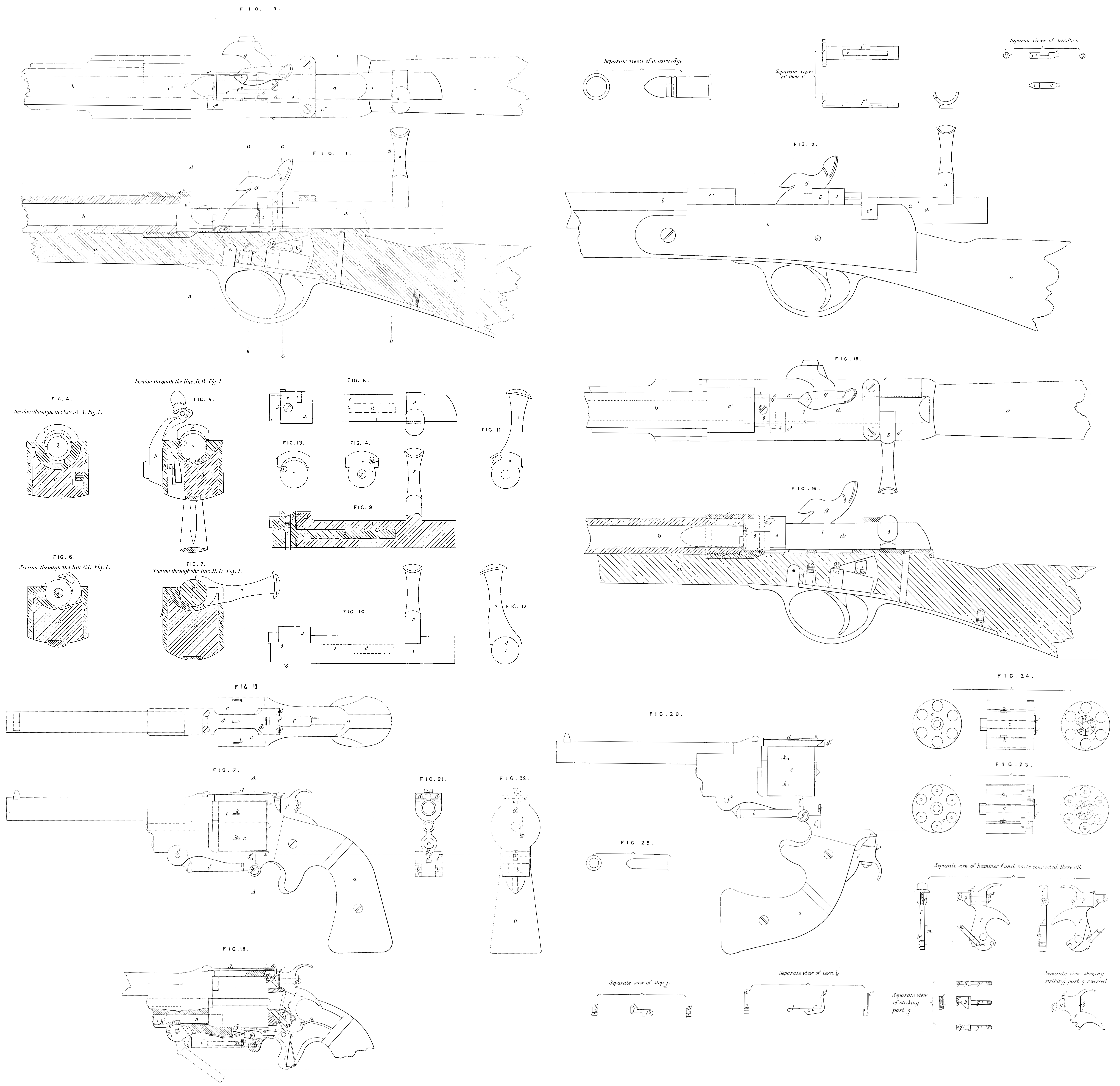
Figure 1 shows a longitudinal section; Figure 2 a side view; Figure 3 a plan; and Figures 4, 5, 6, 7, 8, 9, 10, 11, 12, 13, and 14, other views of parts of a gun constructed according to the first part of my Invention. In Figures 1, 2, and 8 the parts arc shown as they would appear when in position for receiving a fresh charge. Figures 15 and 16 show the parts as they appear when the charge has been forced into the barrel. In each of these views the same letters are employed to indicate corresponding parts wherever they occur.
a, a, is the stock; b, the barrel; c, c, the metal casing; and d, the breech bolt for forcing and holding the charge in the barrel of the gun. This breech bolt d, it will be seen, is formed double by the part 1 embracing the part 2, whilst both parts are capable of sliding to and from the breech end of the barrel of the gun within the cheeks or side surfaces c¹, c¹, of the casing c, and the upper portions of these cheeks extend sufficiently over the bolt d or embrace it to an extent to prevent the possibility of that bolt flying upward when a charge is fired, When the breech bolt d is drawn back, as shown by Figures 1, 2, and 3, a chamber is formed between it and the breech end of the barrel of the gun to receive a charge, as shown by the red lines in some of these Figures. The sliding of the breech bolt is effected by means of the handle 8 formed on the part 1, and when a charge has been placed in position, as indicated by the red lines in Figures 1 and 3. the breech bolt is slided between the parts c¹, c¹, by acting on the handle 3 until the charge is fully driven into the breech end of the gun, as shown by the red lines in Figure 16, when the bolt d may be securely held in position, by turning the handle 3, with the outer shell or case 1 of the breech bolt € on the inner part 2 thereof, so as to bring the handle 3 fully into the recess ¢* formed for it in the frame, and the projection 4, which is also formed on the part 1, into the recess c³ in the case c, when a secure abutment will be obtained to bear against the enlarged end 5 formed on the internal part 2 of the bolt d, and hold that enlarged part 5 securely in the housing b¹ formed for it in the breech of the barrel of the gun against the charge, and so as to enable it to resist the firing of such charge. This enlarged end 5 of the breech bolt d is formed to fit closely into the housing b¹, and it carries a needle c, by striking one end of which with the hammer the other end thereof will be forced against the percussion end of the charge placed in the barrel to explode that charge. But if desired a nipple may he formed on this piece 5 to receive a cap, or the needle ¢ may be bored through and be formed as a nipple to receive a cap at its upper end. The inner end of the enlargement 4 is formed with a recess, so that that enlargement may not bear against the needle c; this recess also serves as a chamber to_enclose or cover the end of the needle next to it when the bolt is being withdrawn from the barrel, so that the end of the needle to be acted upon by the hammer is only exposed when the parts are in position for the hammer to act thereon; f is a fork formed on the bar f¹, and attached to the bolt d, so as to move to and fro with that bolt by the projection G thereof acting at either end of the slot f² formed in that bar f¹; this fork stands up in front of the cartridge in the barrel of the gun, and when the bolt is withdrawn it pulls out the spent cartridge. g is the hammer; in going forward to strike the needle the striking end of this hammer g also bears against the enlargement 4 with a tendency to lock that bolt against its return, and thereby to give increased security in using the gun. The breech end of the barrel b is secured by screwing into a rim or ferrule c*, forming part of the metal casing c, and it is in this ferrule that the housing or enclosure b¹ is formed. The bolt i, forming one of the bolts by which the lock plate h is secured to the metal casing and to the stock, also serves as an axis for the catch h¹ to the trigger of the lock, In some cases I apply a spring to the arm of the sliding bolt with a tendency to keep it turned in its groove.
In carrying out the second part of the Invention, in place of the conical or bullet end of the cartridge being formed solid, I form that end of paper or other suitable material, of form and consistency to fit the bore of the gun but to enclose a number of shot, the cover thereof being such that will admit of the separation of the shot on leaving the gun; when for a rifled barrel these cases will pass into the grooves forming the rifling of the gun, and the effect will be to impart a rotary motion to the contained shot, whilst it protects the grooves of the rifle from the injurious action of the shot. Cartridges thus formed arc applicable to various descriptions of fire-arms.
Figure 17 represents a side view of a pistol constructed according to the third part of my improvements; Figure 18 shews part of the same view in section; Figure 19 shews a plan view; and Figure 20 shews a side view of the pistol when open for a change of charge cylinder or for the supply of fresh charge to such cylinder; Figures 21 and 22 are end views of parts looking in opposite directions from the line A, A, Figure 17.
The butt a is connected to the fore part of the pistol by a hinge joint b, which, as shown, is situated at or near the back end of the charge cylinder c, and the parts are held in position for firing, as indicated by Figures 17, 18, and 19, by means of a spring catch d, affixed to the fore part of the pistol; this spring catch d is at its end d¹ turned down to catch on to the projection e of that part of the pistol connected to the butt; the hammer f is also formed at f¹, so that in striking the part f¹ comes over the catch d!, with a tendency more securely to hold the parts together at the instant of firing. By the use of the hinge & increased facility is given for the change of charge cylinders or for charging such chambers or applying caps. Charge cylinders of different kinds may be used with the same fire-arm, as, for instance, such as have the charge applied at the fore end of each chamber, and from which the charge is fired by caps on nipples at the rear end of these chambers, or such as have their chambers bored through to receive the charge from the rear end of them, and in which the charge is fired by a self-contained percussion powder.
Figure 23 shows three views of a charge cylinder adapted to the use of percussion caps, and Figure 24 shows three views of a charge cylinder for receiving the charges containing their own percussion compound. And in order to provide for the use of percussion caps or charges containing their own percussion powder the hammer f is formed with a double-striking part g, which is capable of being turned so as to present either of its surfaces g¹ or g² for action. The surface g¹ is for acting on caps, the surface g² for acting on charges, such as shown by Figure 25, with the percussion powder. in the rim thereof, The plate g is held in position by a set screw g³ but this may be varied. A is the ramrod, which slides in a passage formed for it, and it has teeth h¹ formed on it, which are taken into by a segment of teeth i formed on the arm i¹, and capable of turning on the centre of motion i², by which the ramrod h may be moved to and fro opposite a charge chamber to force in a charge at the front end of a charge chamber, or when the charge has been applied at its rear end to aid in forcing out the discharge case. The arm i¹ is held up to keep the ramrod back, when not in use, by the spring stop i³. The charge cylinder is held correctly at each partial rotation with a chamber opposite the bore of the barrel by a spring stop j entering any one of the recesses k formed for it in the surface of the charge cylinder; this stop is formed on the lever arm j¹, which turns on a centre j², and is borne upwards by a spring j³, and the stop j is withdrawn at the time of effecting a change of chamber by the pressure on the lever j¹ of one end of the lever l, which turns upon a centre of motion l¹, and at its other end l³ is acted upon by a stud l² from the side of the hammer, the stud l³ being inclined or chisel edged, to admit of that end of the lever l² passing in one direction and catching to pull thereon when “cocking.” m is the driver, attached by pin joint m¹ to the hammer for acting on the catches c¹ of the barrel to give a step-by-step motion to it. The driver m is acted upon by a spring n to keep: it in position.
Having thus described my improvements, and means which I adopt in carrying the same into effect, I would have it understood that | do net confine myself to the precise details shown and described, as these may be varied without departing from the peculiar character of the Invention, but what I do claim is, —
First, the application of a double breech bolt and parts acting therewith, formed and operating in manner substantially as explained.
Also I claim the application of a fork and parts acting therewith, for the purpose of removing the spent cartridges in the act of withdrawing the breech bolt to supply a fresh charge, in manner substantially as explained.
Also I claim the mode of arranging and combining parts, whereby the hammer in going forward to strike serves also to lock the outer portion of the breech bolt and also as an abutment to the inner portion of such breech bolt, substantially as described.
Also I claim the arranging and combining parts whereby the bolt which secures the lock plate to the metal easing and to the stock serves also as an axis for the catch to the trigger of the lock, substantially as described.
Secondly, I claim the manufacture of conical or bullet-ended cartridges, as described.
Thirdly, I claim in relation to that description of fire-arms in which charge cylinders are employed containing a series of charge chambers, the connecting the butt ends of such fire-arms to the other parts thereof by a hinge joint at or near the back end of the charge cylinder, in manner substantially as explained.
Also I claim the application to such description of fire-arms of a spring catch d, and parts acting therewith, arranged and operating substantially as described.
Also I claim the arranging and combining parts in such description of fire-arms by which the hammer at the time of firing acts upon a suitable catch, with a tendency to hold the parts safely together at such time, substantially as explained.
Also I claim forming the hammer with changeable striking parts, adapted to the firing of different descriptions of charges, substantially as described.
Also I claim the mode of arranging and combining parts for operating and fixing the ramrod, as described.
Also I claim the mode of arranging and combining parts for retaining and releasing the charge cylinder as required, in manner substantially as explained.
In witness whereof, I, the said Thomas Jefferson Mayall, have hereunto set my hand and seal, this Eleventh day of October, in the year of our Lord One thousand eight hundred and sixty-five
THO. J. MAYALL. (L.S.)