
US Patent 7629
Cylinder stops, safety pins, fouling grooves on arbor
UNITED STATES PATENT OFFICE.
SAMUEL COLT, OF HARTFORD, CONNECTICUT.
IMPROVEMENT IN REVOLVING CHAMBERED FIRE-ARMS.
Specification forming part of Letters Patent No. 7629, dated September 10, 1850.
To all whom it may concern:
Be it known that I, SAMUEL COLT, of Hartford city and county, in the State of Connecticut, have invented certain new and useful Improvements in Revolving Chambered Fire-Arms; and I do hereby declare that the following is a full, clear, and exact description of the principle or character which distinguishes them from all other things before known, and of the method of making, constructing, and using the same, reference being had to the accompanying drawings, making part of this specification, in which-
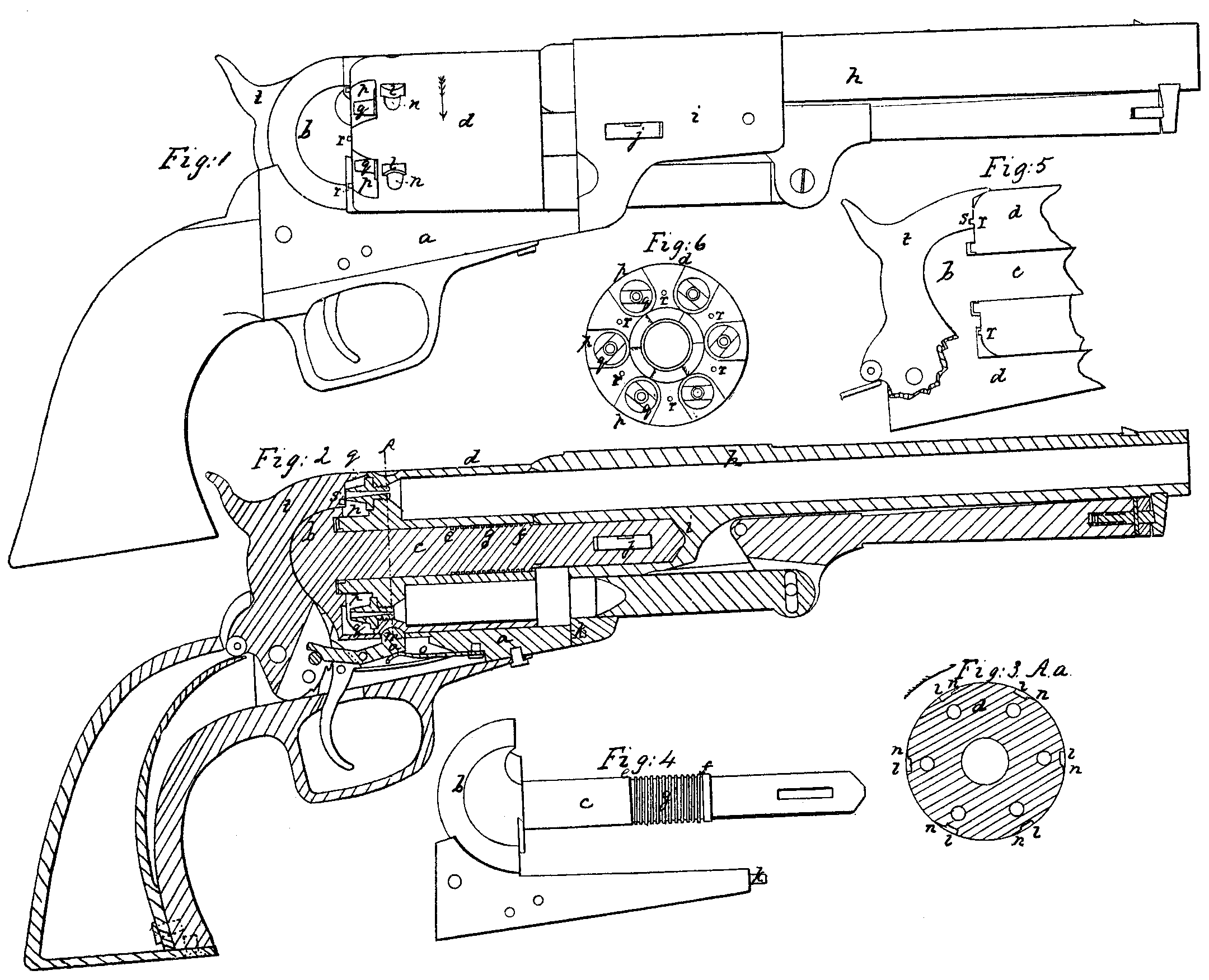
Figure 1 is an elevation of a pistol on my improved plan; Fig.2, a longitudinal section; Fig. 3, a cross vertical section taken at the line A a of Fig. 2; Fig. 4, a separate representation of the recoil-shield, the lock-plate, and the spindle on which the rotating breech turns; Fig. 5, another longitudinal section through the spindle, rotating breech, and cock to show the manner of holding the rotating breech by the cock between the chambers; and Fig. 6, an elevation of the rear part of the rotating breech.
The same letters indicate like parts in all the figures.
My present invention relates to improvements on the revolving chambered fire-arms secured to me by Letters Patent bearing date on the 25th day of February, 1836, and on the 29th day August, 1839, in which the charges are contained in a series of parallel chambers made in a rotating breech-piece, which is so connected with the barrel and with the lock that by the operation of cocking the hammer the breech is unlocked and rotated to bring a new charge in the line of the barrel and relocked preparatory to the discharge. The rotating breech turns on a spindle projecting from the recoil-shield, and the barrel is secured to the forward end of this spindle and rests against the end of the lock-plate. The rotating breech is locked for each discharge by the end of a bolt that enters in succession a series of holes in its periphery. When firing rapidly – that is, in working the arm quickly to bring each chamber in succession in the line of the barrel – the holes which are intended for the reception of the locking-bolt are carried beyond the end of the said bolt by the momentum, so that the chambers are not brought and held in the line of the barrel. This either prevents the discharge or strains the arm as the ball is forced by the discharge from the chamber into the barrel.
As heretofore constructed, when the arm is at rest the cock rests against the cap on one of the nipples, and in this position, if by accident a blow be given on the back of the cock, the cap is liable to be exploded, and thereby a load discharged, which may be productive of serious consequences.
The object of my present invention is to remedy these evils; and to this end the first part of my invention relates to the method of insuring the true and accurate position of the breech at the end of each shift of the chambers preparatory to the discharge, and consists in combining with the holes which receive the end of the locking-bolt elongated grooves of less depth and extending from one hole toward the next throughout the series, so that the end of the locking-bolt, which enters by a spring and is withdrawn by the lock, shall enter the elongated grooves and be within the surface of the rotating breech before the chamber is brought to the line of the barrel, and thus be in a position to insure the stoppage of the breech when it reaches the line of the barrel, and then enter the locking-hole before it can rebound or turn back. By this means the arm can be operated with the utmost rapidity without any danger of having the barrel out of its true line at the time of the discharge. And the second part of my invention, which relates to the manner of locking the breech when the arm is at rest to prevent accidental discharges, consists in locking or holding the rotating breech mid-way, or nearly so, between any two of the chambers by a hole in the face of the cock or hammer fitting onto a projection of the rotating breech, or vice versa. By this means, if the cock or hammer be struck when the arm is at rest, no explosion can take place, as the hammer in that position is not in contact with either of the nipples, which, with the breech so situated, are effectually protected by the shield-plate.
In the accompanying drawings, a represents the lock-plate, to which is properly secured the stock, &c.; b, the shield-piece, from the center of which projects a spindle, c. The parts a and b are made from one block of metal cut or worked out to the required form for adaptation to and reception of the various parts of the arm. The spindle c is firmly secured to or made a part of the shield-piece, and is adapted to the central bore of the rotating chambered breech d, and its periphery at e and f is formed with two parallel grooves running in the direction of the periphery, and these are connected by a helical groove, g, so that smoke and other impurities which have a tendency to pass between the spindle and the bore of the rotating breech are arrested by these grooves, which are made square and with sharp edges, so that they shall scrape the bore of the breech when rotated to shift the chambers, and thus scrape off the solid matter deposited by the smoke and collect it in the grooves, so that until these grooves are filled there will be no tendency to clog the spindle and bore of the breech, which otherwise would take place after a few discharges. This arrangement also prevents the fouling of the lock.
Instead of grooving the periphery of the spindle, the grooves may be made in the inner periphery of the cylinder.
The barrel h has a projection, i, which is made with a socket to fit onto the end of the spindle, and is there secured by a key, j, the end of the spindle being made to bear against the bottom of the socket, so as to determine the distance to which the barrel shall be forced or carried toward the cylinder by the securing-key, and thus prevent the binding of the barrel against the end of the rotating breech, while the key insures a close joint to prevent the escape of lateral fire.
The periphery of the chambered breech is provided with a hole, l, for each chamber, which at the proper time receives the end of a bolt, m, for locking and holding the breech in its proper place during each discharge. The breech which rotates in the direction of the arrow (it may rotate in the reverse direction) has grooves n, running in the direction of the periphery, of less depth than the holes l, and extending, one from each hole toward the next, in the direction of the rotation, so that when the breech is rotated the spring lock bolt m, which is liberated after the breech has commenced its rotation by the action of a spring, o, enters a groove, n, leading to the next hole, and hence the moment that the next chamber comes in a line with the barrel it is arrested by the bolt m, which, having entered the groove is within the periphery of the rotating breech, and there enters the hole, which is of greater depth than the groove, and will therefore prevent the breech from turning back. These grooves are inclined to the periphery, commencing at each hole and gradually running toward the periphery of the rotating breech.
On the rear end of the rotating breech, and in the spaces between the recesses p in which the nipples q are secured, there are projecting pins r, one for each space. The face of the hammer t is formed with a hole corresponding to and of sufficient capacity to receive and hold one of these pins r, so that when the arm is to be put in the state of rest the hammer or cock is slightly elevated and the breech turned until the hole in the face of the hammer will fit into one of the pins r, which locks in the barrel in such a position that the hammer cannot strike either of the nipples.
Instead of having the pius or projections r on the breech and the hole in the hammer, this may be reversed by making a projection on the face of the hammer and corresponding recesses in the rear of the breech.
What I claim as my invention, and desire to secure by Letters Patent as an improvement for fire-arms having a rotating breech with a series of parallel chambers, is-
1. In combination with the locking-holes of rotating chambered-breech fire-arms, substantially such as herein specified, making grooves leading to each locking-hole, substantially in the manner and for the purpose specified, when this is combined with a bolt independent of the mechanism which rotates the breech, and which bolt enters to lock by a spring and is withdrawn by its connection with the lock, substantially as described.
2. Holding the rotating breech midway, or nearly so, between any two of the chambers, to prevent accidental discharges, by means of a recess or hole in the hammer or cock fitting on to a projection of the rotating breech between any two of the chambers, or vice versa, substantially as herein specified.
SAML. COLT.
Witnesses:
WM. BISHOP,
ALEX. PORTER BROMLE.