
US patent 1304
Revolver and Revolving rifle
UNITED STATES PATENT OFFICE.
SAMUEL COLT, OF PATERSON, NEWJERSEY.
IMPROVEMENT IN FIRE-ARMS AND IN THE APPARATUS USED THEREWITH.
Specification forming part of Letters Patent No. 6,384, dated August 29, 1839.
To all whom it may concern:
Be it known that I, SAMUEL COLT, of Paterson, in the county of Passaic and State of New Jersey, did obtain Letters Patent of the United States for an Improvement in Fire-Arms, which Letters Patent bear date on the 25th day of February, in the year 1836, and that I have made certain improvements in the construction of the said fire-arms, and also in the apparatus for loading and priming the same; and I do hereby declare that the following is a full and exact description of my said improvements.
My first improvements appertain to rifles, guns, and pistols; my second to the construction of a cap-primer for containing the percussion-caps and placing the same upon the nipples, and my third to a flask and other apparatus for loading the rifle or gun.
For the general construction of my fire-arms, as originally patented I refer to the Letters Patent first above named, the same being necessary to a perfect understanding of the improvements thereon, which I am now about to describe.
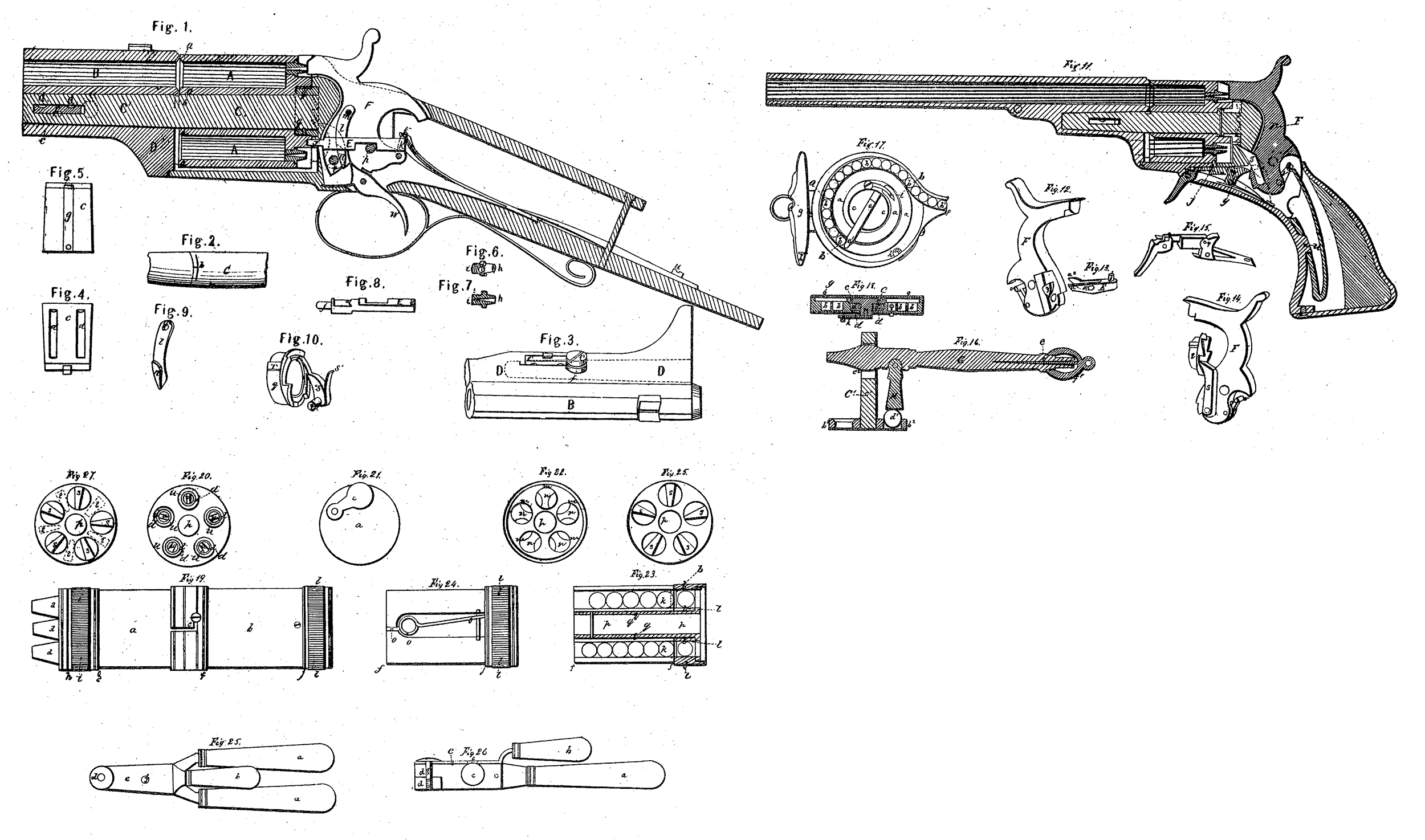
Figure 1 in the accompanying drawings represents a section through the lock and breech of my rifle or gun and two of the chambers of the revolving receiver, B being a part of the barrel of the gun. The mouths of the chambers and the end of the barrel have their edges chamfered or beveled, as shown at a a in the drawings. In all guns of this description there is necessarily a lateral discharge between the receiver and the barrel, and this lateral discharge may endanger the ignition of the powder. in the loaded chambers not in contact with the barrel; but the ignited matter, by coming into contact with the beveled edge as it crosses said chamber, is effectually reflected off, and does not enter them. The beveling of the end of the barrel is not a thing of importance, it being intended merely to prevent its scraping or cutting the ball in its passage from the chamber.
Fig.2 shows a part of the arbor upon which the receiver turns. b is the portion thereof which is immediately below the chamber in contact with the barrel, and in this part a channel or groove is made descending from the point b in both directions, so as to form two inclined planes meeting at the point b. These planes or sections of the grooves may form an angle at forty-five degrees with each other. This groove or channel serves as a chimney to conduct off the smoke of the lateral discharge, so that it shall pass directly between the receiver and the barrel and prevent its spreading, so as to pass in between the receiver and the arbor and the barrel and the arbor, and consequently from condensing there and rendering them foul. The barrel is connected with the receiver and with the stock of the gun by the aid of the arbor which at the rear end, is a solid piece with the shield or solid piece of metal which receives the recoil and constitutes a component part of the metallic frame-work or foundation of the lock and its appendages. The part C of the arbor is that upon which the receiver revolves, and the part C’ enters a cylindrical cavity in a mass of iron, D D, to which the barrel is brazed or otherwise attached.
Fig. 3 shows the piece of iron D D and a part of the barrel B which is attached to it. The dotted lines in this represent the cylindrical cavity which receives the outer end of the arbor C’. The two are keyed together by the passing of a suitable key through a mortise in the piece D D, and a corresponding one in the arbor.
c, Figs. 1, 3, 4, and 5, represents the key. Fig. 4 shows its upper and Fig. 5 its underside. d d are two fluted channels along its upper side to receive the heads of two screws which are screwed into, the piece D D close to the mortise and on the side opposite to that shown in Fig. 3. The heads of these screws lap a little over the mortise and are received into the fluted channels dd. These heads prevent the key from falling out and check it in either direction, and must be withdrawn in order to remove the key. As the key c is to act laterally as a wedge to draw the receiver and the barrel into proper contact, it is of importance that it should be checked when forced sufficiently far in, or the receiver night be Wedged up and prevented from turning. For this purpose I insert a screw, e, Fig. 3, into the steel button f, which is attached to D D, to strengthen the end of the mortise and prevent the bruising of it by the recoil. The head of this screw, overlapping the end of the mortise, receives the wedge and checks it. By turning this screw the force of the wedge may be tempered. In Fig. 5, g is a spring-latch on the under side of the key, which catches upon D when the key is forced in and prevents its accidental removal.
Fig. 6 represents a percussion tube or nipple, through which the fire from the percussion-cap is to be conducted to the chamber. Fig. 7 represents the same in section. The outer end, l, of the tube has the opening made as large as convenience will allow, and it goes tapering or conical until at the inner end, i, it is as small as a proper entrance of the flame from the percussion-powder will warrant. By giving the conical or funnel-formed opening-to the tube the effect of the percussion-powder is greatly increased.
E, Figs, 1 and 8, is a bolt for locking the receiver when a loaded chamber is brought to coincide with the barrel, the rounded end j being forced into a hole in the receiver by the action of a spring on its outer end k. This bolt is drawn back by the hammer F in the act of cocking.
l, Figs. 1 and 9, 1s a spring-cam, which is screwed to the hammer at m. It is made of spring-steel, so that its cam end in may recede from or approach the hammer F. The cam n bears against the projection o on the bolt E on the side which lies against the hammer, and as the hammer is drawn back causes the bolt to recede. The bolt is notched to enable it to be withdrawn without interfering with the joint-pin q of the hammer. The lateral springing of the cam-piece l is necessary to admit of its passing by the projection o of the bolt when the hammer is made to strike upon a percussion-cap. To enable the spring-cam to pass the bolt E, the lower end of it, n, is made Wedge-shaped, diminishing to a point or edge at its extremity, and as it is made to spring laterally it is received into a recess in the hammer as the latter passes the bolt in making the discharge.
Fig. 10 shows the ratchet-wheel and hand or pawl by which the receiver is made to revolve to the distance from one chamber to another in the act of cocking. The cylindrical periphery g of the ratchet-wheel fits into a corresponding cavity on the back end of the receiver, as shown at g g Fig. 1. r is a projection to prevent its turning round, this being adapted to a notch made to receive it. S is a hand or pawl, which falls into the teeth of the ratchet-wheel, said pawl being forced forward by the spring S’. The arbor t on which the hand turns is received into the opening t. In the hammer, Fig. 1, the hand itself being on the opposite side of said hammer from that shown, its position is shown by the dotted lines surrounding its arbor t. The cocking of the gun causes it to act upon the ratchet-wheel, and when turned to the proper distance the bolt E is forced by its spring into the proper the stock and upon which the receiver turns, opening in the receiver. The mainspring is connected to the lock-plate at u, and to the hammer by a stirrup at V. The trigger is shown at w. These parts, not differing in their construction and operation from analogous parts in other gun-locks, need no particular description, and from the description above given of the structure and operation of those parts of the rifle or gun which are new, the action of the whole will, it is believed, be clearly understood.
Fig. 11 is a sectional view of a pistol, the general construction of which is the same with that of the rifle or gun already described, such modifications only being made as are rendered necessary by its size and other considerations. F is the hammer carrying the hand or pawl S, which operates on the ratchet-wheel, which wheel and hand are arranged in the same way with the same parts in the rifle; but the hand is as here represented on the reverse side. The bolt which holds the receiver is, however, differently constructed to enable. it to act in the space which it must occupy.
Fig. 12 is a view of the hammer on the side the reverse of that shown in Fig. 11; and E, Fig. 13, is the bolt adapted thereto, j is the pin on the bolt, which holds the receiver by falling into openings on its periphery instead of in its end. The pin j is shown in place in Fig.11. The bolt E vibrates on a joint-pin at x, which is nearly in the same line with the joint-pin y on the trigger, Figs. 11 and 15, by which it is hidden in those figures. z is a cam formed in a recess in the hammer, Fig. 12, which cam is to act upon the bolt E and to disengage it from the receiver. The ends a’ a^2 of this bolt are capable of receding from or approaching toward each other, as they constitute two spring-cheeks formed by splitting or forking the bolts, as shown in the drawings. The end a lies above the cam z on the hammer when the pistol is not cocked, and the lower end of a, as well as the upper end of a, being flat, the bolt E is lifted in the act of cocking until the pin j is disengaged, and the ends of a^2 and z then pass each other. The cam z is made wedge shape by sloping from its upper to its lower end, and the end a” of the bolt is similarly formed, but in the reverse direction, so that when the piece is discharged the end a will be made to spring in, allowing the hammer to pass readily, when the end a^2 again rests upon 2 as before.
Fig.14 shows the hammer with the hand S and ratchet g, which need no further description.
Fig.15 shows the trigger and its appendages, which are formed in a way not presenting any claim to novelty. u is the attachment of the mainspring to the lock-plate, and v its attachment to the stirrup and hammer.
Fig. 16 shows the apparatus which I employ for forcing the balls into the chambers. b^2 b^2 are two of the chambers, shown in section; and C, the arbor by which the barrel is attached to the stock and upon which the receiver turns, as already explained. G is a lever carrying a rammer, H, by which the balls are to be forced into the chambers. The forward end of the lever H passes into the mortise c^2, which receives the key by which the barrel is attached. The operation of the rammer H upon the ball d’ will be apparent. In using this lever the receiver is to be turned upon the arbor, and the chambers brought in succession under the rammer. This lever, at its end e’, constitutes a wrench for screwing and unscrewing the percussion-tubes, and also contains a picker attached to a screw-cap, f’. A fulcrum for the lever H may be formed on the barrel or otherwise, instead of using the mortise c^2, if preferred.
Figs. 17 and 18 are a top and sectional view of my improved cap-primer, which differs in some important particulars from the English and other cap-primers now in use. I make a spiral groove, a a a, in a plate of brass or other metal, which groove is of such depth and width as to receive the percussion-caps, and to allow them to move freely therein. b b b are caps within said groove. In the center of the primer, under the-plate cc, is a spiral spring, d d, operating like the mainspring of a watch upon its barrels and turning the plate c c. This plate has a groove across, it which carries a sliding arm, e e’, having under its end e’ a projecting piece which enters the groove, draws the aim out, and presses upon the row of caps. At the mouth of the spiral groove, where the the cap b’ is seen, a steel spring, f, checks the cap and counteracts the pressure of the spiral spring d d; but when the cap b’ is placed upon the tube or nipple the spring f will recede by the withdrawal of the cap, and a new one will be made to occupy its place, and so on until the whole are exhausted. The cover g, which in Fig. 17 is shown as raised, is held down by a spring-catch at h. There is a spring-catch at i, which holds the sliding arm at its end e’, when it is brought round to the inner end of the spiral groove, its use being to detain the arm while the groove is being filled with caps, when it is to be raised, and the arum left at liberty to operate. The spring d d may be wound up by a small key, k, or by inserting a screw-driver in a notch made for that purpose, or simply by forcing the arm e e round until it is caught by the catch i.
Fig. 19 is a representation of my ammunition-flask, by means of which all the chambers in my receiver may be simultaneously charged with powder and with balls. It consists of two separate chambers, one of which is a powder and the other a bullet magazine, a being the former and b the latter, the two-being connected together by a bayonet-joint at c. d d d are charging-tubes adapted in number and position to the mouths of the chambers of the receiver which they are to enter.
Fig. 21 shows the closed top of the powder-magazine, with a valve or turn cover, e, which closes a hole through which the magazine is to be filled. This magazine occupies the space from f to g, Fig. 19, where the powder is contained in bulk. The space from g to h is a receptacle which is divided by partitions into separate chambers, the same in number with the tubes did, each of which chambers contains the quantity of powder required for the charge of a single chamber, i i is the rim of this chambered receptacle, which is capable of being turned round to a short distance by the thumb and finger for the purpose of charging the chambers with powder. This turning round brings openings u u, Fig. 20, in the lower end of the chambered box to coincide with the openings in the tubes d d, so that the powder contained in the chambers in i i may pass out therefrom into the chambers of the receiver. There are openings also in the upper plate or top of the receptacle i i corresponding with openings in the bottom of the magazine a, which are closed by turning the rim i i, so as to prevent powder from falling through from the magazine while the receiver is being filled.
Fig.27 is a section through the middle of the chambered receptacle ii, the circles r r representing the chambers for containing the powder. s s are the openings in the top plate of these chambers through which the powder is admitted into them from the magazine a. The dotted lines t t show the plan of the openings in the bottom plate of the chamber a, the chambered receiver being shown in the position in which those openings are covered.
In Fig. 28 the same parts are represented; but the chambered receiver is supposed to be turned round or standing in its ordinary position, so that the openings S S and t t coincide. The chambered receptacle is restored to its place by means of a spring of any suitable form. The whole operation of this part will be more clearly made known by the sectional representation of the magazine for balls, which I am now about to describe.
The end of the flask, Fig. 19, is, I have said, the magazine for balls. Fig. 22 is an end view of this magazine, and Fig. 23 a section along its axis. The portion from f to j, Figs. 19, 23, and 24, is divided into as many tubular chambers as there are chambers in the receiver— say five. These are open at top and are to be filled with balls, as shown at k kin the section Fig. 23. These tubes are also open at their lower ends, so that the balls may pass from them into a chambered receptacle, l l, similar to that for the powder. From this chambered receptacle they are to fall into the chambers of the receiver when the lower end of the flask, Fig. 22, is applied thereto for that purpose, the openings m m in the lower end of the flask being adapted thereto. The rim of the chambered receiver l l is to be turned round to allow the balls, to escape through m m, as already described in the charging with powder. In Fig. 22, n n are the divisions between the chambers of the chambered receiver, and which, retain one set or tier of balls until the rim is turned around so as to cause the chambers to coincide with the openings m. m. The balls will then pass through. The same motion of the chambered receiver causes the divisions between the tubes and the chambered receiver to pass, under and sustain the balls in the magazine. In the case of the powder-magazine the action is the same; but the powder being in fine particles, the apertures at one end of the receptacles must be perfectly closed before those at the other begin to be opened, which is not necessary with the balls. In Fig. 24 a portion of the exterior of the magazine is removed to show how a spring, o o, may be placed within it so as to act upon l l; but spiral or other springs may be placed in many ways to answer the same purpose. The central part of both the magazines is tubular, as shown at pp, said tube fitting onto the arbor C, Fig. 16, when the barrel is removed therefrom, and the receiver left on for the purpose of being charged, which operation does not require to be further explained. Upon the barrel of this tubular part the chambered receptacles are received and revolve.
Figs. 25 and 26 represent a top view and a side view of a part of an improved bullet-mold, which I describe without intending to make any claim thereto, but merely for the purpose of showing the whole of the apparatus employed in a complete and connected series. a a are the two handles of the mold, and b the handle of the knife by which the sprue is cut off. c is one-half of the mold, of which d d is the binge-joint. e is a plate of steel, through which there is a hole, f, for pouring in the lead, the lower edges of which constitute a knife by which the sprue is cut off and the ball left perfect. This knife turns on the joint-ping.
Having thus fully described the manner in which I construct and use my improved firearms, and the respective articles of apparatus appertaining thereto, it has been necessary in so doing to mention many parts which I do not claim as new, the same being similar to what has been before used and patented by me, or which are common property. I do hereby declare, therefore, that I limit my claim to the following particulars.
I claim—
1. The making of a groove or channel on the arbor, as represented at b, Fig. 2, for the purpose of conducting off the smoke from the lateral discharge, and thus preserving the arbor clean within the receiver, and the tube by which the barrel is connected.
2. The particular manner of forming and governing the key by which the barrel is attached to the stock by making the same with grooves in which the heads of overlapping screw-heads are received, and with a tempering-screw to check and regulate its action as a wedge, as set forth.
3. The making the aperture through the tubes or nipples (which receive the percussion-caps) conical or funnel-shaped, for the purpose of freely admitting the fire from the percussion-cap and concentrating it as it enters the chamber.
4. The manner. of arranging the bolt E of the rifle and its spring can l n for locking and unlocking the receiver, the same being constructed and operating as herein described.
5. The manner of constructing and arranging the bolt E and its spring calm, operated upon by the cam or projecting piece z under that modification thereof adopted in the pistol, and herein fully made known.
6. The improved manner of arranging the ratchet-wheel and hand, as set forth, by which the hinge joint to allow of the lateral motion of this hand, as described by me in my former patent, is dispensed with in consequence of the placing of the ratchet-teeth on the face instead of on the side of the wheel, and operating the same in the manner described, as applied to the rifle and to the pistol.
7. The combination of the lever with its rammer for forcing the balls into the chambers of the receiver, as described.
8. In the improved cap-primer, the making thereof with a spiral groove to receive the caps, and with the sliding arm acted upon by the spiral spring elongating itself and forcing the percussion-caps forward in the manner set forth.
9. The manner of constructing and arranging the respective parts of the magazines for powder and balls, in the flask, by means of which the powder and the balls are in turn supplied to all the chambers in the receiver at the same time, the whole being made with the chambered receptacles and other parts, as set forth.
SAML. COLT.
Witnesses:
Thos. B. Jones,
George West.