
US 421798
UNITED STATES PATENT OFFICE.
DANIEL B. WESSON, OF SPRINGFIELD, MASSACHUSETTS.
BARREL-CATCH MECHANISM FOR FIRE-ARMS.
SPECIFICATION forming part of Letters Patent No. 421,798, dated February 18, 1890.
Application filed July 6, 1889. Serial No. 316,669. (No model.)
To all whom it may concern:
Be it known that I, DANIEL B. WESSON, a citizen of the United States, residing at Springfield, in the county of Hampden and State of Massachusetts, have invented new and useful Improvements in Barrel-Catch Mechanism for Fire-Arms, of which the following is a specification.
This invention relates to improvements in barrel-catch devices for fire-arms of the “breakdown” class, particularly revolvers, the object thereof being to provide a spring-catch device for the locking of the barrel on the frame when the barrel, with relation to the frame, is in its proper position for firing which device will be simple of construction, effective and durable in use, easy of manipulation, and compact, and in no way unsightly in its disposition on the fire-arm; and the invention consists in the construction and combination of parts, all substantially as will hereinafter more fully appear, and be set forth in the claims.
Reference is to be had to the accompanying drawings, forming part of this specification, in which similar letters of reference indicate corresponding parts in all the views.
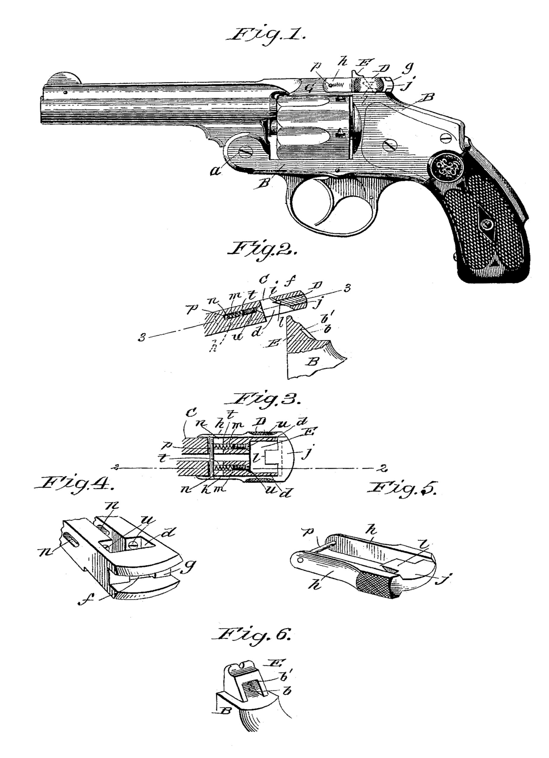
Figure 1 is a general side view of a revolver with the improved barrel-catch of this invention applied thereon. Fig. 2 is a vertical sectional view, on a larger scale than that on which the preceding figure is drawn, through a portion of the frame comprising the catch-post and through the rear portion of the barrel-strap and a part of the barrel-catch, said latter parts being shown as swung out of engagement with the catch-post. Fig. 3 is a horizontal sectional view of the parts last above mentioned, said parts, however, being shown in their positions of engagement. The horizontal plane of section through the barrel-strap and barrel-catch on which Fig. 3 is taken is indicated by the line 3 3, Fig. 2, while the vertical plane of section through said parts on which Fig. 2 is taken is indicated by the line 2 2, Fig. 3. Fig. 4 is a perspective view of the barrel-catch detached. Fig. 5 is a perspective view of the rear portion of the barrel-strap, and Fig. 6 is a perspective view of the catch-post on the frame of the fire-arm.
As usual in this class of fire-arms, the barrel A forward of and below the cylinder is pivotally connected to the frame B, said barrel being provided with a strap-extension C, extended rearwardly therefrom and over said cylinder and adapted to rest on the part of said frame above and to the rear of the cylinder, and through the barrel-catch D on the barrel-strap engaging with the catch-post E on said frame. The barrel is confined in its proper position for firing, as shown in Fig. 1, from or out of which position, however, the barrel is to be swung on the frame for the purposes of loading or otherwise.
The catch-post E, which is formed integrally on or attached to the frame, is generally of the form shown in Figs. 2 and 5, having its rear side curved or inclined forwardly and upwardly, corresponding to a line generated from the pivotal point a between the barrel and frame, and said catch-post in its rear side is provided with a notch or recess b, having a horizontal upper wall b’.
The barrel-strap C is apertured near its rear end from top to bottom, the form of which aperture d is such as to closely fit by all its side walls over said catch-post. The rear end wall of the barrel-strap has an opening f there-through leading into the aperture d, and the rear end portion of the said barrel-strap is also formed with a horizontal transverse channel g, extending through from side to side thereof, whereby the upper and lower lugs g’ g’ are formed.
The barrel-catch D consists of a stirrup-shaped piece which horizontally embraces the rear end portion of the barrel-strap, the bifurcated members h h of which barrel-catch lie along the sides of the barrel-strap, while the rear transverse uniting portion j lies against the rear end of said barrel-strap, being normally disposed within said transverse channel g, and said transverse uniting member j is provided with a forwardly-extending latch-lug l, having a horizontal top i, from which it recedes downwardly and rearwardly, as particularly shown in Figs. 2 and 4, and said barrel-catch lug is adapted to be projected through the opening f in the end wall of the barrel-strap and to engage by its horizontal top with the horizontal upper wall of the notch in the catch-post. Springs are applied in relation to said stirrup-formed barrel-catch for maintaining said catch in its normal and forward disposition on the barrel-strap, an approved construction and arrangement thereof being as follows: The barrel-strap in advance of the vertical aperture d, by which it fits over the catch-post, is horizontally and longitudinally bored, whereby one or more sockets m—in practice two—are formed. The barrel-strap also has formed horizontally therethrough from side to side thereof a slot n, which intersects the forward ends of said longitudinal sockets, the longitudinal extent of said slot relative to the length of the barrel-strap being as great as the extent of longitudinal play necessary for the barrel-catch. A pin p passes transversely through and between said members h h of the stirrup-formed barrel-catch and through the forward end of said horizontal slot n of the barrel-strap, and a spiral spring t is placed in each of said longitudinal sockets m of the barrel-strap, bearing by its forward end against said transverse pin p, each of said springs being held in place by a screw-plug u, entered a short distance into the rear end of the socket. With the apertured barrel-strap fitting over the catch-post and the latch-lug l of the barrel-catch engaging the recess in said catch-post by merely forcing rearwardly on the said spring-pressed and stirrup-shaped barrel-catch the engagement of the barrel-strap with the catch-post is released, and the barrel may be readily swung on the frame.
What I claim as my invention is—
1. Barrel-catch mechanism for fire-arms, consisting of a catch-post on the frame, having a notch therein, combined with a strap extending rearwardly from the barrel, having an aperture near its rear end, whereby it may fit over said catch-post, and having an opening leading to said aperture through the rear wall thereof, and a forwardly-spring-pressed barrel-catch adapted to embrace and slide on the rear portion of said barrel-strap, comprising a latch-lug adapted to project through
said rear-wall opening of the barrel-strap into an engagement with the notch of said catch-post, substantially as set forth.
2. Barrel-catch mechanism for fire-arms, consisting of a catch-post on the frame having a notch therein, combined with the barrel-strap having the aperture d near its rear end and having the opening f leading to said aperture through the rear wall thereof, said barrel-strap also being provided with one or more longitudinal sockets and a transverse slot intersecting the forward end thereof, a spiral spring confined in each of said longitudinal sockets, and the barrel-catch of stirrup form having the rear transverse member thereof provided with the forwardly-projecting latch-lug l and having the pin p, carried by the side members thereof, passing through said transverse slot and across the forward portion of each longitudinal socket in advance of the spring therein, substantially as and for the purpose described.
3. In a barrel-catch mechanism for firearms, the barrel-strap having the aperture d and opening f and one or more longitudinal sockets m and the transverse intersecting slot n, a spiral spring in each socket, and a screw-plug u, closing the outer end thereof, combined with the stirrup-formed barrel-catch having the transverse pin p, all arranged for operation substantially as and for the purpose described.
4. In a barrel-catch mechanism for fire-arms, the barrel-strap having the aperture d, the opening f, leading to said aperture through the rear wall thereof, and the transverse channel g in said rear wall, combined with the forwardly spring-pressed barrel-catch of stirrup form; the side members of which lie along the outer sides of said barrel and the rear uniting transverse member thereof being normally disposed in said channel and provided with the forwardly-projecting latch-lug, substantially as described.
DANIEL B. WESSON.
Witnesses:
WM. S. BELLOWS,
H. A. CHAPIN.