
US 285862
UNITED STATES PATENT OFFICE.
DANIEL B. WESSON, OF SPRINGFIELD, MASSACHUSETTS.
LOCK FOR REVOLVING FIRE-ARMS.
SPECIFICATION forming part of Letters Patent No. 285,862, dated October 2, 1883. Application filed June 25, 1883. (No model.)
To all whom it may concern:
Be it known that I, Daniel, B. Wesson, of Springfield, in the county of Hampden and State of Massachusetts, have invented a new and useful Improvement in Revolving Fire Arms, of which the following is a specification and description.
The object of my invention is to locate the hammer and all the upper portion of the lock mechanism entirely within the frame, so that the latter at its upper part may be entirely closed, with no apertures through which to admit dirt, and so that the desirable symmetrical proportions and form of the handle or “grasp” may be preserved, and whereby the blow from the hammer against the firing-pin, in exploding the cartridge, may be at any desired point along the firing-pin between its pivot and its free end, according to the location of the hammer-pivot, and also to prevent a revolving fire-arm, more particularly that class known as “self-cocking revolvers”, from being accidentally or prematurely discharged; and I accomplish this by the mechanism substantially as hereinafter described, and illustrated in the accompanying drawings, in which—
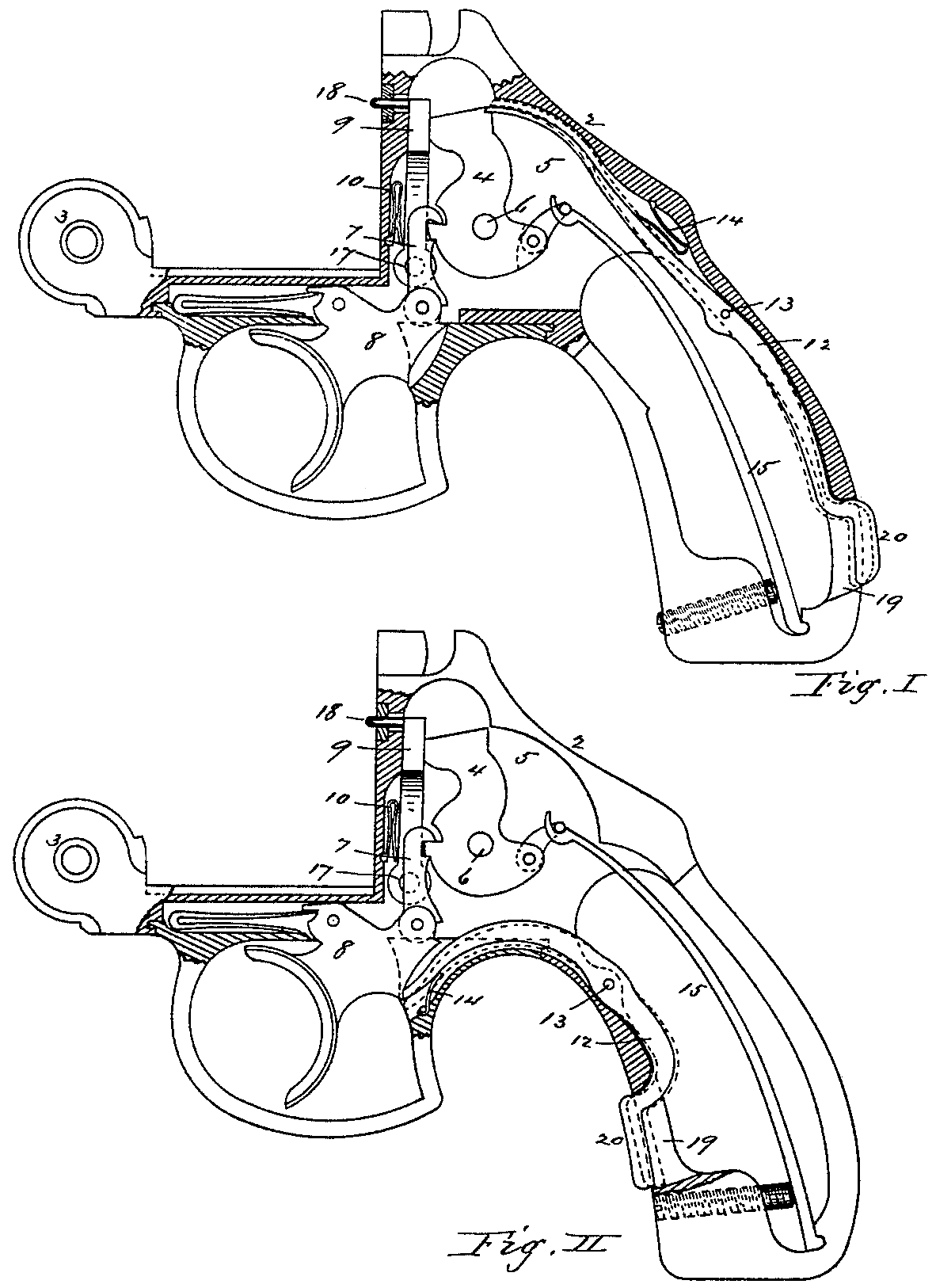
Figure I is the side view of the frame of a self-cocking revolver, with a portion thereof in section, showing the arrangement of the lock mechanism and my invention applied thereto, and with the safety-lever arranged to operate in connection with the hammer portion of the lock mechanism; and Fig. II is a modification of the same, showing the safety-lever arranged to operate in connection with the trigger.
In the drawings, 2 represents the frame of a self-cocking revolver, with the hammer 4 pivoted therein at 6, and the frame recessed inside at 5, to permit the hammer to swing back on its pivot and entirely within the limits of the handle portion of the frame, so that no portion of the hammer projects through or beyond the handle in its movements upon its pivot 6.
The trigger 8, dog 7, pivoted to the trigger and engaging with the hammer to cock it, and the hammer 4, the latter being connected with its mainspring 15 by its stirrup, comprise the main parts of the lock mechanism, and which are well known, except that in this construction I make the hammer shorter at the top to accommodate it to its movements required within its recess 5 inside the frame.
At some convenient point in the frame, preferably at 17, I pivot what I denominate an “oscillating firing-pin,” 9, which is adapted to swing backward and forward on its pivot 17 in a plane parallel with the plane of movement of the hammer, and the upper part of this oscillating firing-pin is provided with a projection or pin, 18, which, when the hammer is thrown forward and is pressing against the firing-pin, projects through the upper part of the frame; but when the pressure of the hammer is withdrawn or the hammer is moved back— as when the hammer rebounds or is partially or wholly cocked— a small spring, 10, placed between the frame and the firing-pin, forces the latter hack also, so that the projection or pin 18 does not then project through the frame.
It sometimes happens that a revolver is accidentally discharged by careless handling or by pressing against the trigger, if the parts of the lock mechanism are adjusted to operate easily, and accidents are liable to result therefrom. To remove this objection, I pivot a lever, 12, in the top strap, a portion of one arm of which pivoted lever projects through the handle or stock, the end of the other arm of said pivoted lever abutting against or being in a position in rear of the back edge of the hammer, so that the latter cannot swing on its pivot until said end of the lever is raised out of its position in rear of and in reach of the hammer by pressing in the projecting and exposed portion of the other arm of the lever and tilting the latter on its pivot, which may be done by grasping the stock in the land.
In the modification shown in Fig. I, 12 represents a lever, pivoted at 13, inside the top strap of the frame, and the end 20 of whose lower arm projects through an aperture, 19, made through the rear side of the handle, as shown clearly in Fig. I, and the end of the upper arm of this lever 12 is held by a small spring, 14, conveniently disposed in the handle, down in a position directly behind the upper end of the hammer 4. As long as this lever remains in this position no portion of the lock mechanism can be moved to discharge the arm; but if the handle is grasped by the hand, as in the act of firing, the lower exposed end, 20, of the lever 12 will be forced in by the natural pressure of the hand, and the upper end will be raised above the hammer, and the latter is free to be moved back and the arm free to be discharged by the backward pressure against the trigger, the position of the lever 12 in that case being indicated in dotted lines in Fig. I.
Instead of pivoting the lever 12 so that the end of one arm may project through the handle on the rear side and the end of the other arm engage against a rear part of the hammer, as shown in Fig. I, said lever may be pivoted in the bottom strap of the stock or handle at 13, with a portion of its lower arm protruding through the aperture 19 in the lower part of the handle or stock and the end of its upper arm in a position just behind the edge of the trigger 8, so that the latter cannot be pulled to cock the hammer or discharge the arm except when held or grasped in the hand, as in the act of firing, in which case the pressure of the hand against the exposed projecting part 20 of the lever will tilt the latter to disengage its other end from the trigger, and permit the latter to be pulled to operate the lock mechanism, with a small spring, 14, secured in any convenient position, as in the frame behind the trigger in Fig. II, to keep the in closed end of the lever in its position behind the trigger.
A revolving fire-arm constructed in this manner may have its hammer entirely inclosed and operate with the handle or frame, and the arm, not requiring any openings therein for the hammer to move, is not liable to be clogged with dirt.
As the hammer is made somewhat short and blunt, to inclose it entirely within the handle and retain the desired shape and size of the handle or grasp, the firing-pin 9, made in this manner, may also be entirely inclosed within the frame, and be struck by the short hammer, when let off, at any point between the projecting pin or part 18 and the pivot 17, to give the desired blow to explode the cartridge, according as the hammer-pivot is located high or low Within the frame.
It will be seen that a revolving fire-arm provided with my invention cannot be discharged without taking hold of the handle and grasping it firmly, as in the act of firing, although no movement of the trigger is required to disengage the lever 12 from any part of the lock mechanism; and the arrangement constitutes a safety device and a positive guard against the accidental or premature discharge of the arm, and also positively prevents the accumulation of dirt and grit in the lock mechanism, which always occurs in revolving fire-arms having openings therein, connected immediately with the lock mechanism or portions thereof.
Having thus described my invention, what I claim as new is—
1. The combination, with the frame of a revolving fire-arm, of a hammer inclosed and adapted to swing upon its pivot entirely within said frame, and a firing-pin adapted to oscillate upon a pivot and to receive the blow from the hammer at a point between its said pivot and its free oscillating end, substantially as described.
2. The combination, with the lock mechanism of a revolving fire-arm, of a lever pivoted in the stock or handle to tilt therein on its said pivot, one arm of which pivoted lewer protrudes through said handle or stock, so that the exposed protruding part of said lever may be forced in by the ordinary pressure of the hand against the stock in grasping the latter, and the said lever be thereby tilted on its pivot to permit the lock mechanism to move without contact with said tilting lever, substantially as described.
DANIEL B. WESSON.
Witnesses:
T. A. Curtis,
Chas. H. Wood.