
US 26919
UNITED STATES PATENT OFFICE.
WM. H. MORRIS AND CHARLES L. BROWN, OF NEW YORK, N.Y.
IMPROVEMENT IN REPEATING FIRE-ARMS.
Specification forming part of Letters Patent No. 26,919, dated January 24, 1860.
To all whom it may concern:
Be it known that we, William Hopkins Morris and Charles Liston Brown, both of the city, county, and State of New York, have invented a new and useful Improvement in Repeating Fire-Arms; and we hereby declare that the following is a full, clear, and exact description of the same, reference being had to the accompanying drawings, forming a part of this specification, in which—
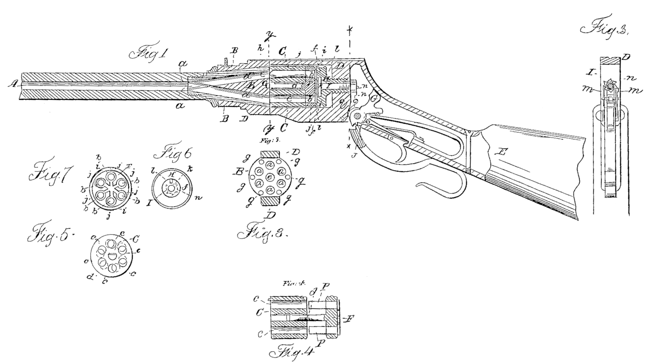
Figure 1 is a central longitudinal section of a rifle with our improvement. Fig.2 is a transverse section in the plane indicated by the line x x of Fig. 1. Fig. 3 is a transverse section in the plane indicated by the line y y of Fig. 1. Fig. 4 is a longitudinal section of the cylinder and the plate by which the discharged cases are withdrawn. Fig. 5 is a transverse section of the cylinder. Fig. 6 is a front view of the recoil-shield and the revolving pin, upon which the hammer acts to explode the charges in the cartridges. Fig. 7 is a rear view of the plate by which the discharged cartridge-cases are withdrawn.
Similar letters of reference indicate corresponding parts in the several figures.
To enable others skilled in the art to make and use our invention, we will proceed to describe it construction and operation.
A is a barrel with a single central bore, having attached permanently to its rear end a concentric cone-shaped piece, B, of steel or other metal, in which are several passages, a a, starting at equal distances apart in a circle described around the rear or base of the cone-piece, from the center thereof, and converging so that all meet at the junction of the cone with the barrel and unite with the bore of the barrel, the said passages forming an angle of about eight degrees with the barrel, so as to unite with its bore without an abrupt bend. The barrel and cone-piece are secured in a stout frame, D, of iron or steel or other metal, to which is secured the stock E, and which is of suitable form to receive within it a cylinder, C, which is arranged with its axis in line with the common axis of the barrel and the cone-piece B, and which contains a number of chambers, c c, corresponding with the number of passages a a in the cone-piece B, said chambers being arranged parallel with the axis of the cylinder and at equal distances apart, so that each may communicate with one of the passages a a of the cone-piece when the cylinder is placed endwise against the rear of the cone-piece. At the rear of the cylinder C there is fitted the circular plate F, which is employed to withdraw the discharged cartridge from the cylinder C, said plate being of about the same circumference as the said cylinder and having a similar number of holes, b b, similarly arranged, and to the front of this plate there is attached a central pin, d, which passes right through a central bore in the cylinder and projects from the front thereof in the form of a journal, e, for the purpose of entering a bearing, e, provided for it in the center of the rear of the cone B, to enable the cylinder to be arranged concentrically to the cone-piece as well as the plate.
In the rear face of the cone-piece B there are a number of holes, g g, into either one of which enters a pin, h, Figs. 1 and 4, that is secured to the front of the cylinder to prevent the cylinder turning and to keep the chambers c c and passages a a, in line with each other. One of the holes g g is sufficient. In rear of this plate there is a screw-bolt, H, which screws in a tapped hole in the back of the frame D, said bolt having its head f, which comes next the plate F, made with a recess to receive within it a projection, i i, in rear of said plate. This screw-bolt serves to force up the plate F close to the rear of the cylinder C, and the cylinder C close up to the rear of the cone-piece B, to make gas-tight joints between those parts. By screwing the said screw back from the plate F the said plate and the cylinder C can be removed together from the frame D.
We propose to employ, in combination with our improvement in fire-arms, cartridges with metallic cases, round the rear of which is a hollow flange filled with percussion powder, said cartridges being inserted in the chambers c c through the holes b b of the plate F from the rear of the latter, and being contained partly in the chambers of the cylinder and partly in the said holes b b, as shown in Fig. 1, where a cartridge is shown in the gun in red color, and the flanges of the cartridges being received in recesses j j, provided for them in the rear of the plate F. The cartridges in the several chambers are to be exploded one after the other in succession by the action of a hammer, G, on the rear end of a revolving pin, I, which is fitted to slide longitudinally as well as rotate within the bolt H, the said pin having a broad head, k, (see Figs. 1 and 6,) on whose face there is a projecting tooth, l, only wide enough to strike one cartridge at a time. This is forced back again by a spring, q, after being struck up by the hammer. The said pin is caused to turn to present the tooth l opposite to a new cartridge, to repeat the fire, by the action upon a ratchet wheel, n, on the rear end of the said pin I, of two dogs, m m, (see Figs. 1 and 2,) attached to a lever, J, which is employed to cock the hammer; but as we do not care in these Letters Patent to claim the devices for cocking the hammer or for exploding the cartridges, we will not further describe them.
The operation of the gun shown in the drawings is as follows: To load, the bolt H is screwed-back far enough to permit the removal of the cylinder C and plate F from the frame D sidewise, and after they are removed the cartridges are inserted through the rear of the plate F into said plate and cylinder, which are then replaced and secured by screwing up the bolt H. When the cartridges are severally fired the balls pass along the passages a a belonging to the respective chambers, and into the common central barrel, by which their flight is directed. After all the cartridges have been fired the bolt H is screwed back and the cylinder C and plate F taken out again, and the plate F is drawn back far enough from the cylinder in the manner represented in Fig. 4 to withdraw the empty cartridge cases p p entirely out of the cylinder, the flanges round the butts of the cartridges enabling the plate to do this. The plate F is then turned a little way round to remove the cartridges from opposite the chambers c c, as shown by the red circles in Fig. 5, and in this position it is pushed forward again, and the front ends of the cases p p, then coming in contact with the rear of the cylinder, are stopped while the plate moves up to the ‘cylinder, and are so forced through the back of the plate, so that they will drop out or can be easily pulled out by the fingers.
By the use in a fire-arm of a series of stationary chambers converging to a common barrel, as herein described, all the advantages of a revolver are obtained without the disadvantages of windage between the cylinder and barrel, and of the liability to get out of order, so common to revolvers; and, besides this, there is no danger of the fire being communicated from one charge to another, as the charges are all protected in front by the balls, and there is perfect safety for the left hand, in firing, Whatever may be its position along the barrel. If preferred, the chambers themselves may converge toward the barrel like the passages a a ; but then the plate F could not be employed to withdraw the cartridges; also, instead of making the cylinder or chambers movable, as in the gun represented, the chambers C may be permanently stationary, and the loading and withdrawal of exploded cartridges effected through a door provided in the back of the frame D, or its equivalent.
We do not broadly claim the invention of side chambers converging into a common discharge-barrel, as they are seen in Lyman’s patent of 1857. The chambers there employed are used as receptacles for powder, to accelerate the discharge of a single ball placed in the central barrel, and the rear portion of the several chambers are separated, having each a separate breech.
What we do claim as new, and desire to secure by Letters Patent, is—
1. The arrangement and combination of the chambers c, whether movable or fixed, the plate F, and bolt H, substantially as and for the purpose herein shown and described.
2. The arrangement and combination of the revolving pin I, bolt H, hammer G, and plate F, substantially as and for the purpose herein shown and described.
3. The employment, in combination with a barrel, A, of a cone-shaped piece, B, having several passages, a a, starting from the base of said cone, and converging so as to discharge into the barrel A, substantially as and for the purpose herein shown and described.
4. The combination, with the cone-shaped piece B, of a cylinder, C, having chambers c c, substantially as and for the purpose herein shown and described.
WILLIAM HOPKINS MORRIS.
CHARLES LISTON BROWN.
Witnesses:
J. Malcolm Smith,
S. Mauris McCord.