
US 264325
UNITED STATES PATENT OFFICE.
DANIEL MOORE, OF BROOKLYN, NEW YORK.
REVOLVING FIRE-ARM.
SPECIFICATION forming part of Letters Patent No. 264,325, dated September 12, 1882.
Application filed March 3, 1882. (No model.)
To all whom it may concern:
Be it known that I, Daniel Moore, a citizen of the United States, residing at Brooklyn, in the county of Kings and State of New York, have invented certain new and useful Improvements in Revolving Fire-Arms; and I do declare the following to be a full, clear, and exact description of the invention, such as will enable others skilled in the art to which it appertains to make and use the same, reference being had to the accompanying drawings, and to the letters and figures of reference marked thereon, which form a part of this specification.
My invention relates to that class of revolving-cylinder fire-arms which are so constructed that a forward longitudinal or other movement of the barrel and cylinder away from the recoil-plate or face of the frame will cause the exploded shells of the cartridges to be simultaneously ejected or drawn from the chambers of the cylinder by means of proper extracting devices.
Revolvers of the class referred to have heretofore been so constructed that when the cylinder and barrel are turned away from the recoil-plate, the hammer is free to act, so that on the return of the cylinder to or near the recoil-plate and before the same has been turned to a locked position, a slight jar or movement of the trigger is liable to cause the discharge of a cartridge before the proper locking of the parts can be effected. The same difficulty and danger is incident to that class of revolvers in which the removal of the cylinder from the recoil-plate is effected by a circular movement or hinge device and the locking of the parts accomplished by means of an extension-strap on the barrel passing over the cylinder and taking over the frame-stud, where it is held by a spring, as it often happens that such spring fails to act, or the movement of the strap may not be made so as to pass to its locked position, the cartridge being thus liable to be discharged while the parts are in an unlocked condition.
I am aware that revolvers have been heretofore made in which the extraction of the shells is effected by a forward longitudinal movement of the cylinder upon the base-pin, the extracting device being a permanently-fixed non-rotating disk that is adapted to seize and hold the flanges of the cartridge-shells.
In this construction much friction is caused by the pressure of the shells upon the periphery of the non-rotating disk-extractors, owing to the swelling of the shells caused by the expansion of the gases generated by their explosion, an increased power being thus required to rotate the cylinder.
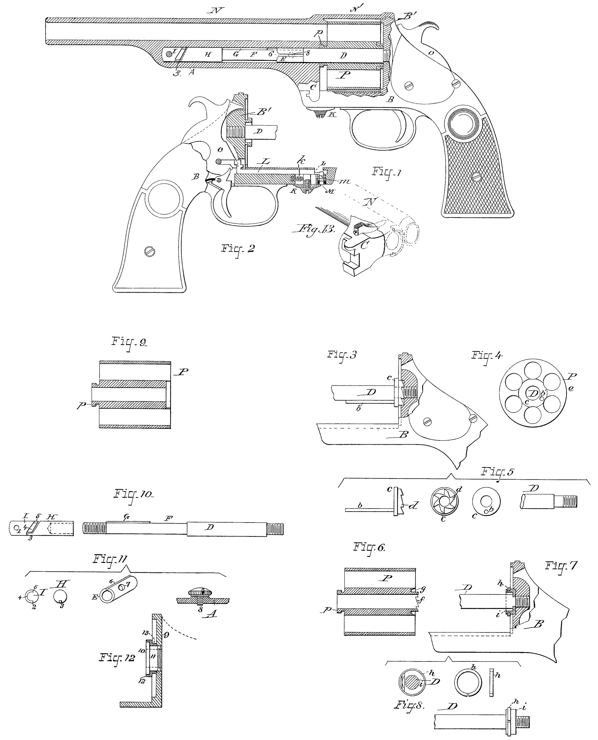
The object of my invention is to obviate the difficulties above referred to and avoid all possibility of an accidental discharge of the fire-arm while the parts are unlocked. This object is accomplished by the mechanism illustrated in the annexed drawings, in which Figure 1 is a side view of my improved revolver, partly in section. Fig. 2 is a sectional detail, illustrating the locking mechanism of the hammer and barrel-bracket. Figs. 3, 4, and 5 are detail views, showing one form of my improved rotating shell-extractor. Figs. 6, 7, and 8 illustrate a preferable form of rotating shell-extractor. Fig. 9 is a longitudinal section of a cartridge-cylinder. Figs. 10 and 1 l are detail views of the base-pin and its connections, and Fig.12 is a modification of the shell-extracting devices. Fig. 13 is a perspective view of the bracket-foot.
Like letters indicate like parts in the several views.
The letter A denotes the barrel-bracket, which is connected with the frame or stock B, as hereinafter described.
C is the bracket-foot; D, the base-pin; and E, a sleeve or collar adapted to slide on the reduced portion F of said base-pin, which reduced portion is adapted to engage with a slot or opening, 6, formed in one side of the collar.
Hi is the enlarged detachable front end of the base-pin D, said parts being connected by a screw-thread and socket, as shown in Fig. 10. The detachable part H is beveled at its front end, which is provided with a projection, 3, as shown in Figs. 1, 10, and 11, for engagement with a separate piece, I, which is secured at the bottom of a cylindrical opening in the barrel-bracket A by means of a screw. The rear end of the piece I is beveled and provided with a semicircular recess, 4, the ends of which form shoulders 2 and 5, that are adapted to engage with the projection 3 on the end of the piece H when the barrel is partially rotated.
K is a slide for moving the locking-bolt L, and M is a spring-stud, which is arranged to hold said bolt to its engagement with the hammer O when the barrel N is rotated, so as to cause the cylinder P to slide forward upon the base-pin in the operation of extracting the exploded shells. When the barrel is returned to its normal position the bracket-foot C, bearing upon the stud M, causes the latter to recede, thus releasing the bolt L from its engagement with the hammer and permitting the front end of the bolt to engage with a recess formed in the bracket-foot, thereby locking the barrel and its bracket securely to the stock B until it is desired to again extract the shells. The springs k and an actuate the bolt L and stud M, respectively, when said bolt and stud are relieved from pressure. The base-pin D is secured to the stock B and recoil-plate B’ in any suitable manner, and the cylinder P and barrel N are connected by a collar, p, as shown in Fig. 1.
In Figs. 3, 4, and 5 is illustrated one form of my improved rotating shell-extractor, in which the extractor c has a series of ratchet-teeth, d, formed on its rear side for engagement with the pawl, by means of which the cylinder is rotated. A rod, b, is attached to the extractor c, and enters an opening, b’, made in the cylinder, which is thus adapted to be rotated thereon by the hammer-action.
The extracting mechanism shown in Figs. 6, 7, and 8 consists of a split ring, h, which is sprung over a piece, i, and takes into a recess turned therein to receive it, being adapted to rotate therein. In this case the rear end of the cylinder is provided with an annular recess, g, within which the parts h and i are fitted, and it also has ratchet-teeth f, that are acted upon by a pawl, which passes up through a recess cut in the side of the part i, as shown in Fig. 8.
Fig. 12 illustrates another mode of constructing my improved rotating extractor, in which the extractor is not made upon the base-pin, nor does it form a part of the frame or stock; but a separate frame, 9, is employed, to which is attached the hub 11, having a flange, 10. Before screwing the hub 11 to the frame-piece 9 a flanged ring, 12 13, is arranged to rotate loosely thereon, and the parts, being connected, as shown, the whole is fixed to the frame of the revolver in any suitable manner.
The operation of the various parts is as follows: The slide K, being drawn or pushed rearward, causes the locking-bolt L to engage with a recess in the hammer, where it is held by the rising of the spring-stud M across its forward end, as shown in Fig. 2. The retraction of the bolt L withdraws its forward end from the recess in the bracket-foot C, and permits the latter to swing out of its recess in the strap or forearm of the frame B. The act of partly rotating the barrel upon the base-pin causes the beveled ends of the parts H and I to engage with each other, thereby drawing forward the barrel and cylinder, thus starting the shells from the cylinder by imparting to the latter a semi-rotary movement before it receives its direct forward movement. In the meantime the sleeve E being held firmly to the bracket A by the screw 8 taking into an opening, 7, formed therein, the cut or slit 6, formed in the side of the sleeve, cones opposite the feather G, which passes therein when the barrel is moved longitudinally forward, and the rotary shell-extractor, taking in front of the flanges of the shells, draws them out of the cylinder-chambers. Any tendency of the shell to bind by expansive pressure upon the periphery of the extractor is overcome by the rotation of the latter. When the cylinder is returned to the recoil-plate and the bracket-foot C swung into position in the recess at the forward end of the frame B the said bracket-foot presses upon the projecting upper end of the stud M, thus forcing it downward, so as to allow the locking-bolt L to be acted upon by its spring k, and thereby caused to enter the recess in the bracket-foot, thus locking the bracket A to the stock B. At this instant the withdrawal of the bolt L from its engagement with the hammer Sets the same free to act as usual. By means of this lock mechanism, it will be observed, the hammer and trigger are positively immovable until the locking-bolt has passed into its proper position and locked the barrel and stock together. This locking device, instead of being arranged as shown, may, if desired, be placed in the upper portion of the frame and so arranged as to take into the end of an extension-strap, N’, on the barrel, the bolt being adapted to engage alternately with the hammer and barrel-strap, so as to produce the same results as those above described.
Having thus described my invention, what I claim as new, and desire to secure by Letters Patent, is—
1. A fire-arm having a rotary ring-extractor located in a recess in the rear end of the cylinder and free to turn in a recess in a grooved boss extending from the recoil-plate, whereby a forward movement of the cylinder away from the recoil-plate will cause the shells to be extracted from the cylinder-chambers, substantially as described.
2. A ring-extractor adapted to rotate upon and in a recess formed in a hub attached to the base-pin or recoil-plate, substantially as described.
3. The combination of the base-pin D, recessed hub i, ring-extractor h, sprung into said recess, and the cylinder P, having recess g and ratchet f, adapted to rotate and slide forward upon said base-pin, whereby a forward movement of the cylinder away from the face of the recoil-plate will cause the shells to be extracted, substantially as described.
4. In a revolving fire-arm, the combination, with the barrel-bracket A and base-pin D, having the part H beveled at its forward end, and provided with projection 3, of the piece I, secured within the bracket and having its rear end beveled and provided with a semicircular recess, 4, forming the stop or shoulder 2 5, whereby a partial rotation of the barrel upon the base-pin brings the beveled ends of the parts H and I into engagement and causes the barrel and cylinder to be carried forward away from the face of the recoil-plate, thereby starting the shells from the cylinder-chambers, substantially as described.
5. In a revolving fire-arm, the combination, with the bracket A and base-pin D, having a reduced portion, F, provided with feather G, of the sleeve or collar E, secured to said bracket and slotted at one side, whereby after the partial rotation of the barrel has brought the feather G opposite the beveled end of the slot 6, formed in said sleeve, the barrel and cylinder are permitted to move forward upon the base-pin, thereby completely extracting the shells from the cylinder-chambers, substantially as described.
6. In a revolving fire-arm, the combination, with the lock-works and bracket-foot of the barrel, of a locking-bolt adapted to engage alternately with each, whereby the rotary movement of the barrel upon the base-pin causes said locking mechanism to automatically secure the lock-works and on the return of the barrel to its normal position automatically releases the hammer and secures the barrel, substantially as described.
7. In a revolving fire-arm, the combination, with the lock-works, hammer O, and bracket foot C, of the bolt L, adapted to engage alternately with each, and the spring-stud M, adapted to hold the bolt to its engagement with the lock-works, substantially as described.
In testimony whereof. I affix my signature in presence of two witnesses.
DANL. MOORE.
Witnesses:
Philip Mauro,
A. R. Brown.