
US 263684
UNITED STATES PATENT OFFICE.
GEORGE W. CILLEY, OF NORWICH, CONNECTICUT.
LOCK FOR FIRE-ARMS.
SPECIFICATION forming part of Letters Patent No. 268,684, dated September 5, 1882.
Application filed March 20, 1882. (No model.)
To all whom it may concern:
Be it known that I, George W. Cilley, a citizen of the United States, residing at Norwich, in the county of New London and State of Connecticut, have invented a new and useful Lock for Fire-Arms, of which the following is a specification.
My invention relates to that class of fire-arms known as “double-acting revolvers,” in which the hammer may be drawn back to full-cock by the use of the trigger alone, although it cannot be set at full-cock by this means, and in which one spring serves to operate the hammer, the trigger, and the revolver-lever, the object being to improve the arrangement of the sickle-lever, in connection with the hammer, and to so combine the sear with the hammer and the trigger that it (the sear) will be held back by an improved device while the hammer is making its stroke. I attain these objects by the mechanism illustrated in the accompanying drawings, in which—
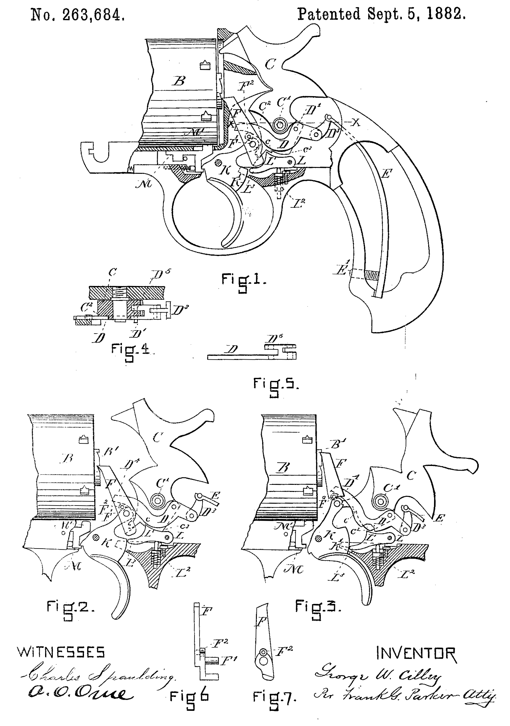
Figure 1 is a longitudinal view, part in elevation and part in section. Fig. 2 is a detail in elevation showing the moving parts at half-cock. Fig. 3 is a detail in elevation showing, the moving parts at whole-cock. Fig. 4 is a horizontal section on line x x of Fig. 1. Fig. 5 is a plan of the sickle-lever detached. Fig. 6 is an elevation of the revolver-lever, Fig. 7 is a side elevation of the same, looking from the back.
The revolver-chamber B, its stop M. M¹, and the ratchet B¹, not being new, need not be described.
C is the hammer, swinging about the pivot C¹. One side of the lower part of this hammer is recessed, as shown at C², the depth of the recess being just sufficient to receive the sickle-lever D, (see Fig. 4) said sickle-lever being pivoted to the hammer C at the point D¹, and connected to the spring E by the link D³.
I obtain a double joint or bearing for the sickle-lever D by forming it with a projection, D⁵ and by connecting it to the hammer by pin, D¹, By this arrangement of passing the pin D¹ through the lever proper and through a portion of the hammer C and then through the projection D⁵, I obtain a double bearing for the sickle-lever to swing upon which will insure its movement in a true plane, and thus prevent it from being twisted out of its position by the strain transmitted to it through the link D8 by the spring E.
Instead of making a kerf in the lower part of the hammer C for the projection D⁵, as shown in Fig. 5, a recess may be made on the rear side of the hammer to receive the part D⁵.
The spring E, acting through the link D³ and lever D, serves to operate the hammer C. It also, through the same means, operates the revolver-lever F, and as the revolver-lever F is pivoted at F¹ to the trigger K it also operates the trigger. The tension of the spring E may be adjusted by the screw E¹.
To lessen the friction of the end D⁴ of the lever D in its action on the lever F, I insert, a friction-roll at F², which is connected to the lever F by a pin or stud passing through it.
L L¹ L³ is a pawl-lever or sear for holding the hammer at half-cock, as shown at Fig. 2.
L² is a piston-spring, which acts upon the sear L L¹ L³ and throws it into the position shown in Fig. 2 and there holds it until the movement of the hammer to full-cock throws it out.
My means for holding the sear L L¹ L³ away from the hammer— that is, the part extending from the half-cock notch c to the point c³— is made in the form of a calm, so that in drawing the hammer back to full-cock, as shown in Fig. 3, the part c³ on the hammer coming in contact with the part L¹ on the sear depresses it, as shown at Fig. 3. Now, when the trigger K is pulled for firing the cusp-point K¹ of the trigger will come in contact with the point L³ of the sear and there hold it until the hammer has made its blow. Then as the trigger is allowed to retreat the sear is thrown back again by the action of the piston-spring L², and is ready to receive and hold the hammer at half-cock. The action of the trigger when pulled back upon the sear L L¹ L³ is to bring the part K¹ against the forward end of the scar, and thus by mere frictional contact hold it from moving in any direction. No part of the trigger comes in lateral contact with the sear, so that the trigger does not under any circumstances move the sear. Its only action on it is to hold it for an instant during the striking movement of the hammer, so that its points, cannot engage with the notch c on the hammer.
The device for holding the hammer at full-cock is not new, and consists in providing the upper end of the trigger K with a notch, k, which engages with the projection c¹, made on the hammer C. (See Fig. 3.)
I am aware that a sickle-lever has been placed in a recess formed in the hammer, it being shown in Patent No. 254,798, granted to me March 14, 1882.
I claim as my invention—
1. The combination of the hammer C, having a lateral recess, C² and the sickle-lever D, having a projection, D⁵, and pivot D¹, whereby a double joint is made between the hammer and sickle-lever, with the link D³ and spring E, all operating together substantially as described, and for the purpose set forth.
2. The hammer. C, having a cam, c c³, the sear-lever L L¹ L³, and spring L², with the trigger K, having a carved portion terminating in a cusp-point, K¹, whereby the sear-lever is held down by friction caused by end pressure substantially as described, and for the purpose set forth.
GEORGE W. CILLEY.
Witnesses:
John E. Warner,
Frank H. Allen.